
Monoblock Filling Machine vs Separate Filler and Capper
A monoblock filling machine can be a good fit when your bottle and closure families work within one proven filling-and-capping platform. Separate machines deserve a closer look when you need to keep an existing filler, change the capping process, or replace stations independently. Neither choice guarantees easier changeovers or better output.
Compare both proposals using the same product, bottles, caps, production schedule, and acceptance test. The useful question is not “Which machine type is better?” It is “Which configuration can handle our actual packs, including changeovers and restarts?”
What Does “Monoblock Filling Machine” Mean?
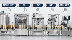
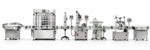
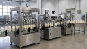
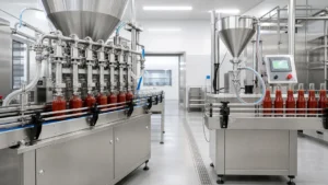
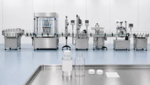
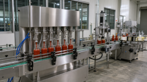
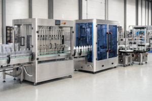
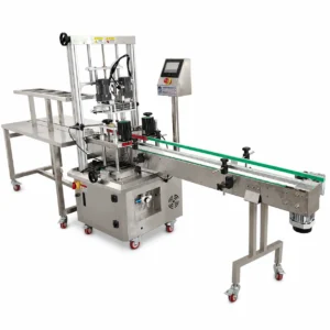
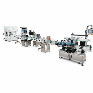
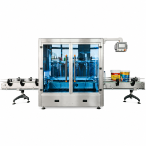
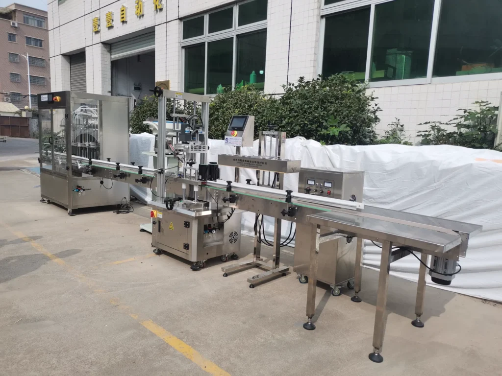
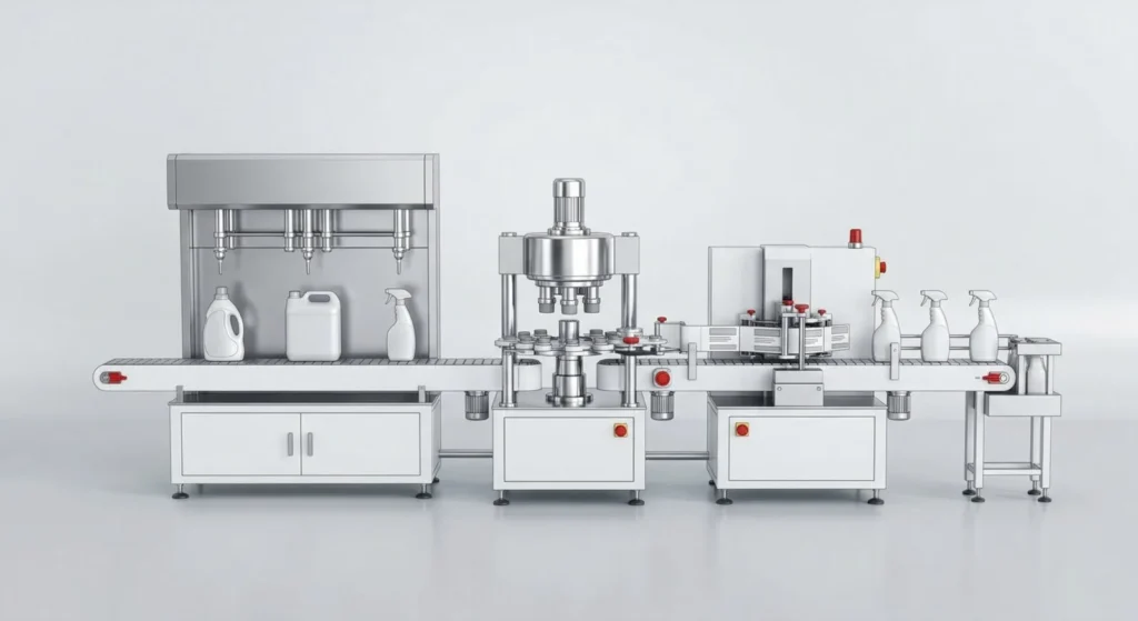
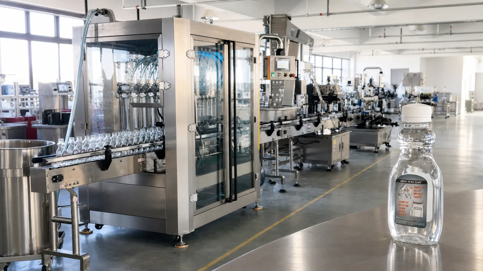
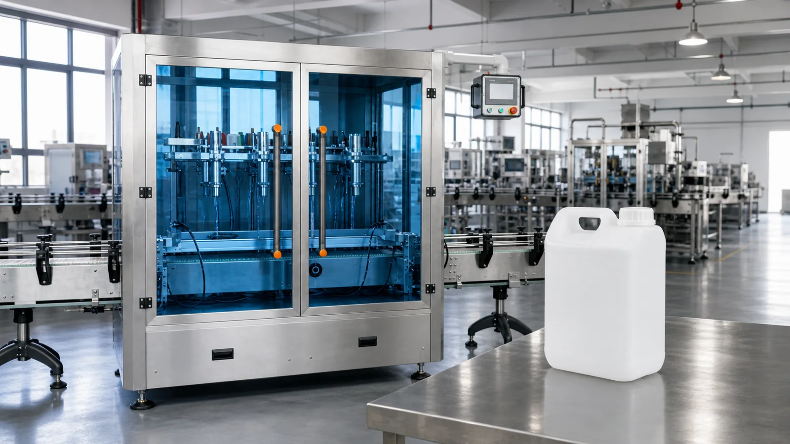
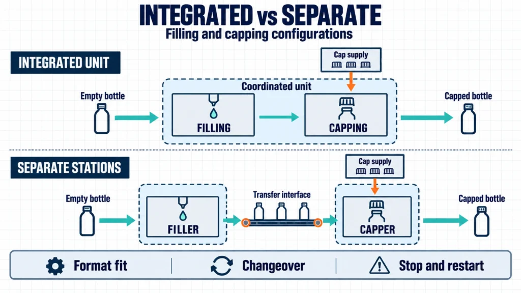
For this comparison, an integrated filling-and-capping machine brings both operations together in one coordinated unit. Separate machines use a distinct filler and capper, with a transfer connection between them. Confirm the actual frame, bottle path, controls, and included operations in each proposal.
Do not infer the whole design from the name. Tirelli describes its Sigma as a monoblock with reciprocating motion and offers manual or automatic cap feeding. Accutek describes its Mini Monoblock as a continuous rotary machine. These are specific designs, not definitions that every supplier follows. [1, 2]
“Inline” is not the opposite of “integrated.” Ask two separate questions: How does the bottle move, and which operations share the machine? Also confirm whether cap sorting and feeding are automatic. Integrated capping does not, by itself, answer that question.
Which Configuration Fits Your Production Plan?
| Production Need | Integrated Filling and Capping | Separate Filler and Capper |
|---|---|---|
| A stable bottle and closure family | A candidate when the complete format is proven on the platform. | Still suitable if transfer and controls are properly matched. |
| Keep an existing filler | Compare the benefit of replacement against keeping useful equipment. | A candidate for adding or replacing the capper; verify the interface. |
| Several very different closures | Require proof of every feeding, placement, and closing process. | Compare dedicated or replaceable capping modules; flexibility is not automatic. |
| Frequent short production runs | Measure the full changeover, including parts and quality checks. | Measure all stations and their transfer adjustments together. |
| Add inspection or sealing later | Check the proposed connection points and controls capacity. | Check available connections, line balance, and responsibility for integration. |
Treat this table as a shortlist, not a purchase decision. Before choosing either structure, confirm that the filling method suits the liquid. Supply the operating temperature, viscosity range, foaming behavior, particles, and relevant chemical information. A machine arrangement cannot compensate for an unsuitable product-contact system.
Start with the Closure, Not Just the Filling Heads
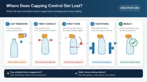
A filler may suit your product while the proposed cap-handling system does not suit your closure. Trace the whole cap journey: loading, sorting, feeding, placement, engagement, and final closing. For pumps or triggers, include the dip tube and required orientation.
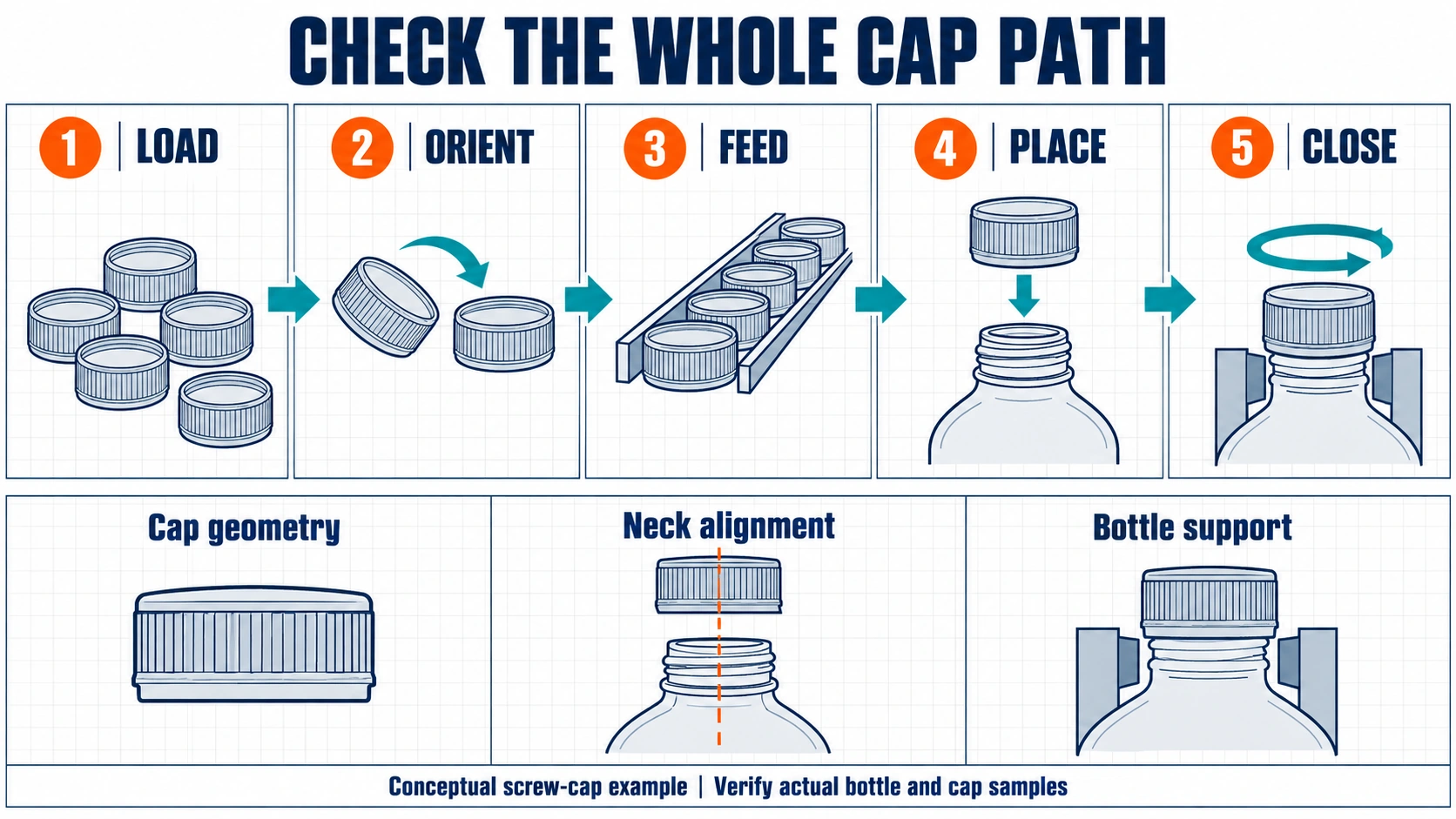
Septimatech documents a cap-positioning case in which an angled cap base affected how the closure sat before pickup. The solution needed a specific pickup and positioning arrangement. The lesson is narrow but useful: cap shape can create a handling problem before tightening even begins. This is a component supplier’s case, not a LEKA installation. [3]
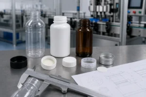
Request a demonstration with your actual bottle-cap pair. Watch how the bottle is held, how the closure arrives, and how it engages. For the package checks behind this step, use LEKA’s bottle and cap compatibility checklist.
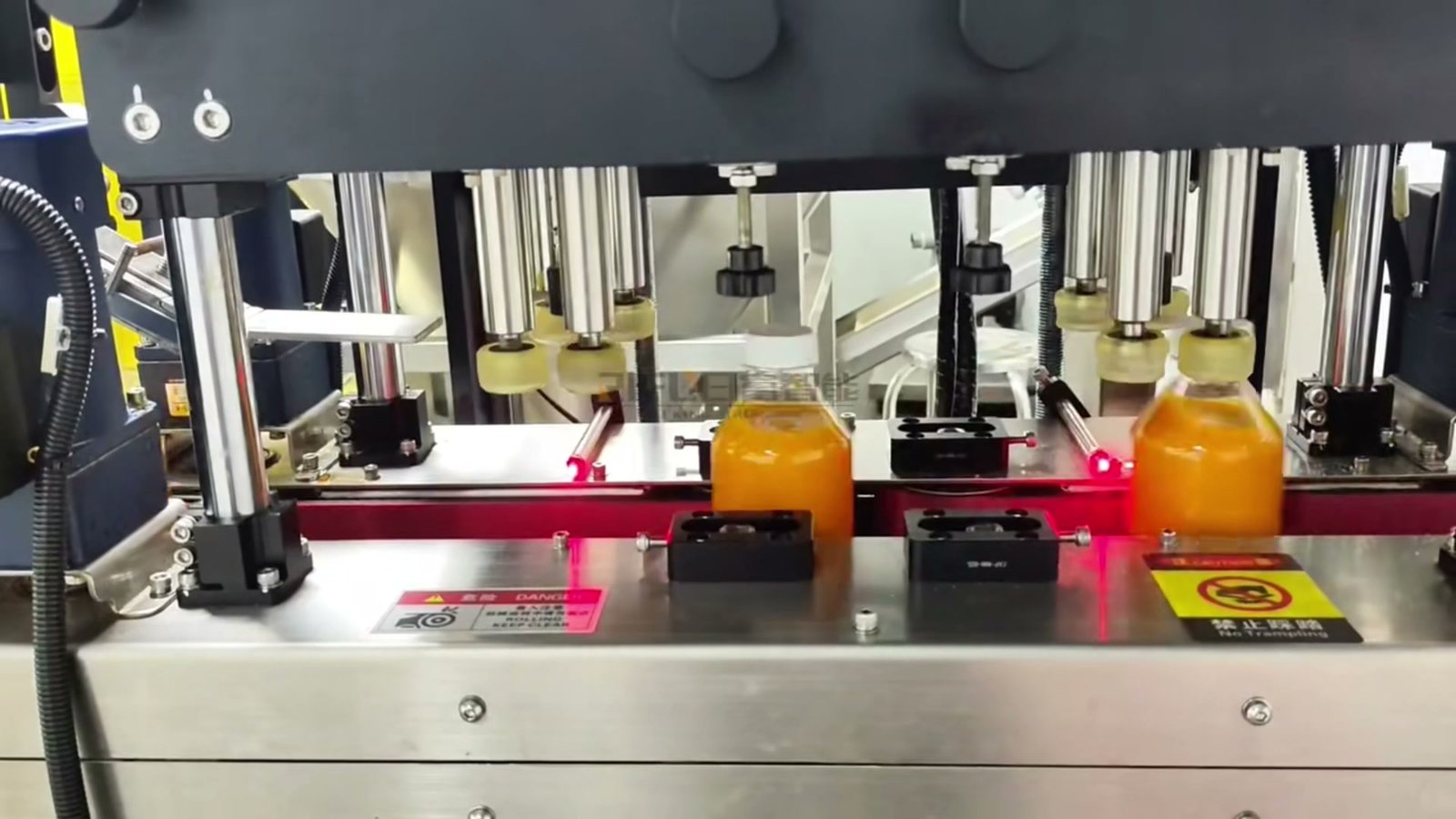
Include real pack conditions in transfer tests. Nercon reports that water-filled sample bottles revealed tipping concerns in a sanitizer conveyor project. Such a handling trial can expose a problem that dimensions alone miss. Water samples do not, however, validate your product’s filling, foaming, or cleaning behavior. [4]
Separate Recipe Changes from Physical Changeover
Tool-less changeover does not mean no change parts. A recipe may set fill volume and timing while bottle guides, locating parts, or cap-handling components still need attention. Septimatech’s change-parts range includes starwheels, guides, positioners, and bottle plates, illustrating the hardware that can be format-specific. [5]
Ask both suppliers to complete the same changeover record for each planned bottle-cap combination.
| Changeover Task | What the Supplier Should Identify | What to Demonstrate |
|---|---|---|
| Recipe settings | Stored fill, motion, and closing settings, where supported. | What loads automatically and what still needs confirmation. |
| Manual adjustments | Guide positions, working heights, sensors, and other adjustable items. | How the operator finds and checks the correct positions. |
| Format parts | Required bottle supports, locating parts, chucks, and cap-feed components. | Which parts are changed, identified, stored, and included in the quote. |
| Production release | Cleaning, setup bottles, fill checks, and closure checks. | When the first acceptable pack is produced and normal running resumes. |
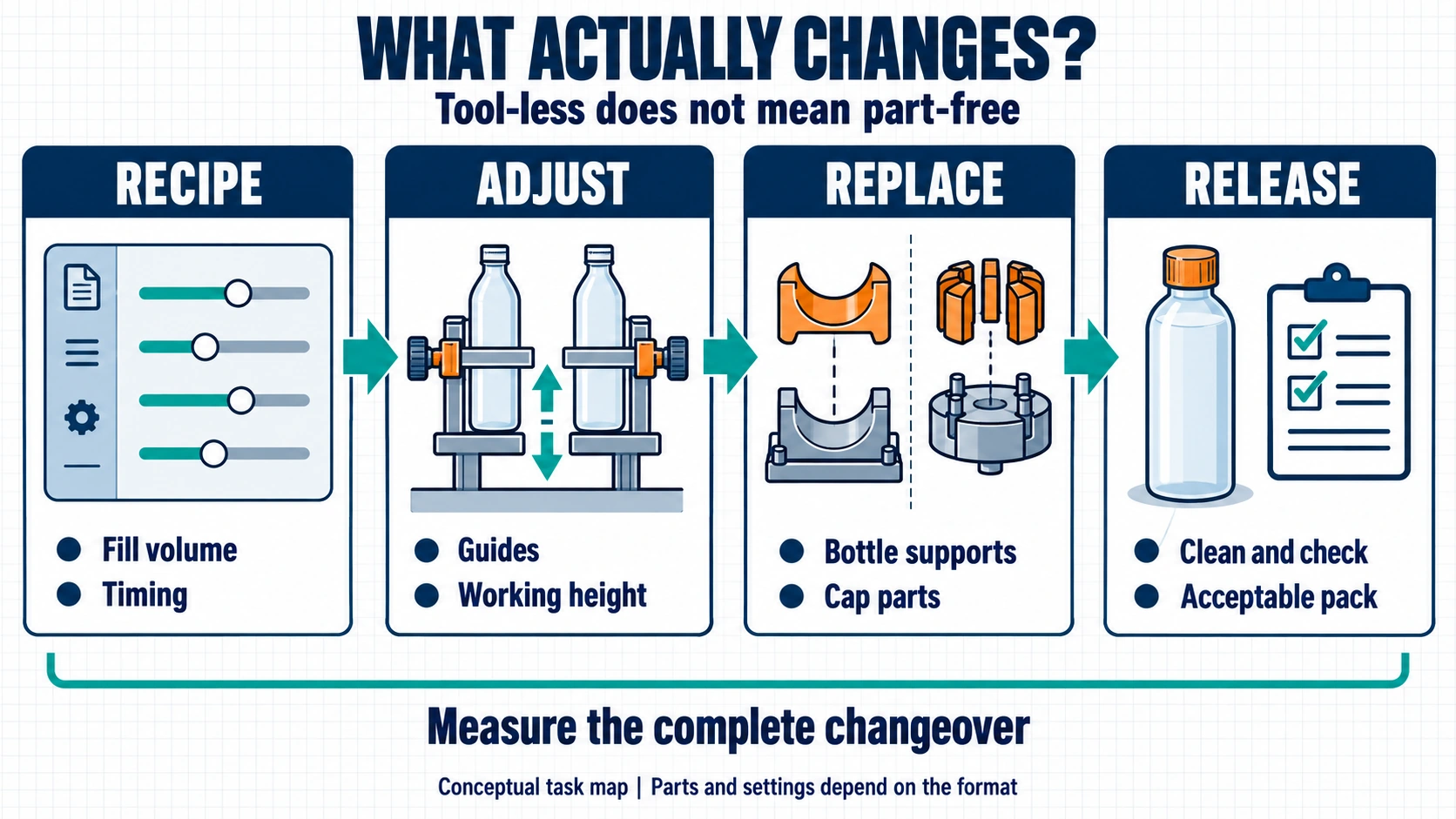
Agree where the changeover clock starts and stops. A demonstration that ends when the operator selects a recipe is not comparable with one that includes cleaning and quality release. Use a demanding planned format change, not only the easiest bottle-size adjustment.
Watch the Line Stop and Restart
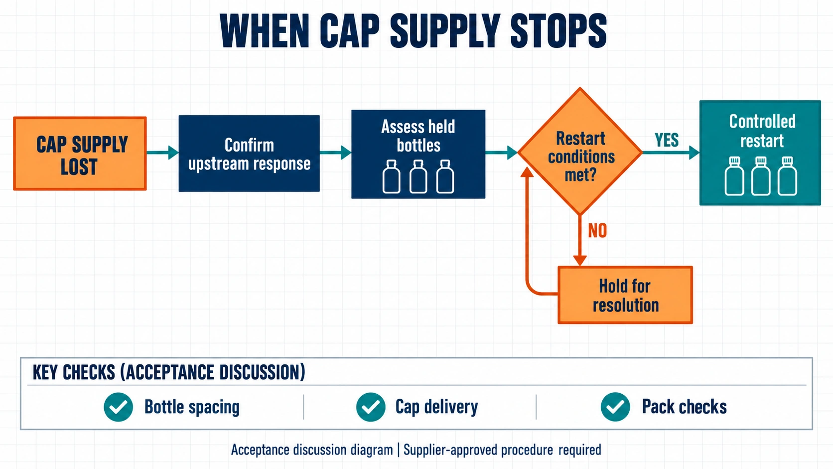
A smooth continuous run is only part of the comparison. Ask the supplier to demonstrate planned stop-and-restart scenarios under an approved procedure. Do not deliberately jam equipment or bypass guards to create a test.
- Cap supply interruption: Which operations pause? What happens to bottles already filled but not capped?
- Downstream equipment unavailable: Where do bottles wait, and what signal stops upstream production?
- Production resumes: How are spacing and cap delivery restored? Who decides whether held bottles need inspection or removal?
For an integrated unit, identify faults that stop both filling and capping. For separate machines, ask the same question: shared controls or a full connecting conveyor may still stop both. Two frames do not prove independent production.
A buffer must solve a defined problem
Do you need to absorb a brief downstream pause, or merely connect two machines? These are different duties. Nercon’s accumulation checklist considers package shape, weight, back pressure, available space, and required accumulation time. Its conveyor guidance also describes a discharge surge when accumulated products are released. [6, 7]
Ask for usable buffer capacity with your packs and a controlled restart demonstration. If the buffer sits between filling and capping, include the condition of the open, filled bottles. Do not assume a system suitable for closed packs is suitable there.
Measure acceptable filled-and-capped bottles at the agreed discharge point, not just filler cycles. Record the format, test duration, rejects, interruptions, and operator tasks. LEKA’s bottle filling machine output guide explains the distinction between filling capacity and complete-line output.
Check Cleaning and Maintenance Access
Neither an integrated unit nor separate machines are automatically easier to clean. Ask for the product-contact path and the cleaning steps for the proposed configuration. Include pumps, valves, hoses, seals, and nozzles, plus access to spills around bottle handling and capping.
If clean-in-place, or CIP, is offered, have the supplier mark exactly which components it covers. Ask what still requires removal or manual cleaning. Do not treat “CIP available” as proof that the entire filling-and-capping area is covered.
For food operations subject to U.S. 21 CFR 117.40, the rules address equipment cleanability and installation that allows cleaning and maintenance. They do not make “monoblock” a hygiene certification. Your team must determine which requirements apply to the product and facility. [8]
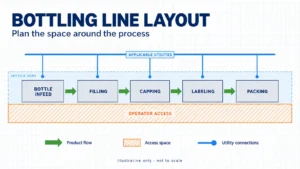
Request access drawings showing guard openings, removal paths, and service points. Have qualified personnel review the maintenance and energy-isolation arrangements. Compare the space needed to operate and service the equipment, not only its base dimensions. See the bottling-line layout guide for the wider floor-plan review.
Compare Complete Quotes, Not Machine Counts
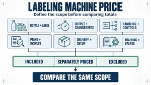
A lower equipment price can be difficult to assess when one proposal includes cap feeding, format parts, and commissioning while another excludes them. Request the same supply boundary before comparing totals.
| Supply Area | Required Confirmation |
|---|---|
| Bottle and cap handling | Included feeders, transfer equipment, format sets, and manual loading duties. |
| Controls and machine interfaces | Named responsibility for signals, stop conditions, restart behavior, guarding, and commissioning. |
| Pack inspection | Included checks, reject handling, and operator verification tasks. |
| Cleaning and maintenance | Supplied cleaning equipment, access provisions, spare parts, and documentation. |
| Delivery and support | Installation scope, training, acceptance tests, and support arrangements. |
For a multi-supplier line, identify who resolves a problem at each machine connection. A useful written question is: “If each machine passes its own test but bottles fail at the transfer, who must correct and retest the connection?”
Compare labor tasks as well. List bottle supply, cap replenishment, quality checks, cleaning, changeovers, and maintenance. A video with nobody standing beside the machine does not establish the staffing needed for a full shift.
Agree on factory and site acceptance
Define the factory acceptance test, or FAT, before ordering. PMMI’s FAT guidance announcement emphasizes clear expectations and acceptance criteria. Then agree on the site acceptance test, or SAT, under the installed conditions. CDA’s explanation distinguishes testing at the manufacturer from testing at the customer’s site. [9, 10]
For this comparison, include the agreed bottle-cap combinations, sustained good output, changeover demonstration, and controlled recovery scenarios. State how site utilities and connections to existing equipment will be checked. Shipping release, final acceptance, payment, and warranty terms should be agreed separately in the contract.
Two LEKA Configuration Paths to Discuss
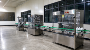
LEKA’s FLX-6TSFA filling and capping machine combines six-head servo filling with an integrated three-claw capping arrangement. It is a starting point for discussing a coordinated unit, subject to review of your liquid, bottle, and closure. It should not be assumed to be a rotary monoblock.
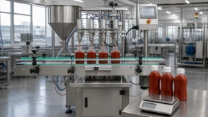
For a separate-station example, LEKA’s Thailand mango juice filling and capping project describes a tracking servo filler combined with automatic cap feeding, capping, and conveying for rectangular bottles. That project concerns pulp-free juice; it is not proof of suitability for juice with particles or a different closure.
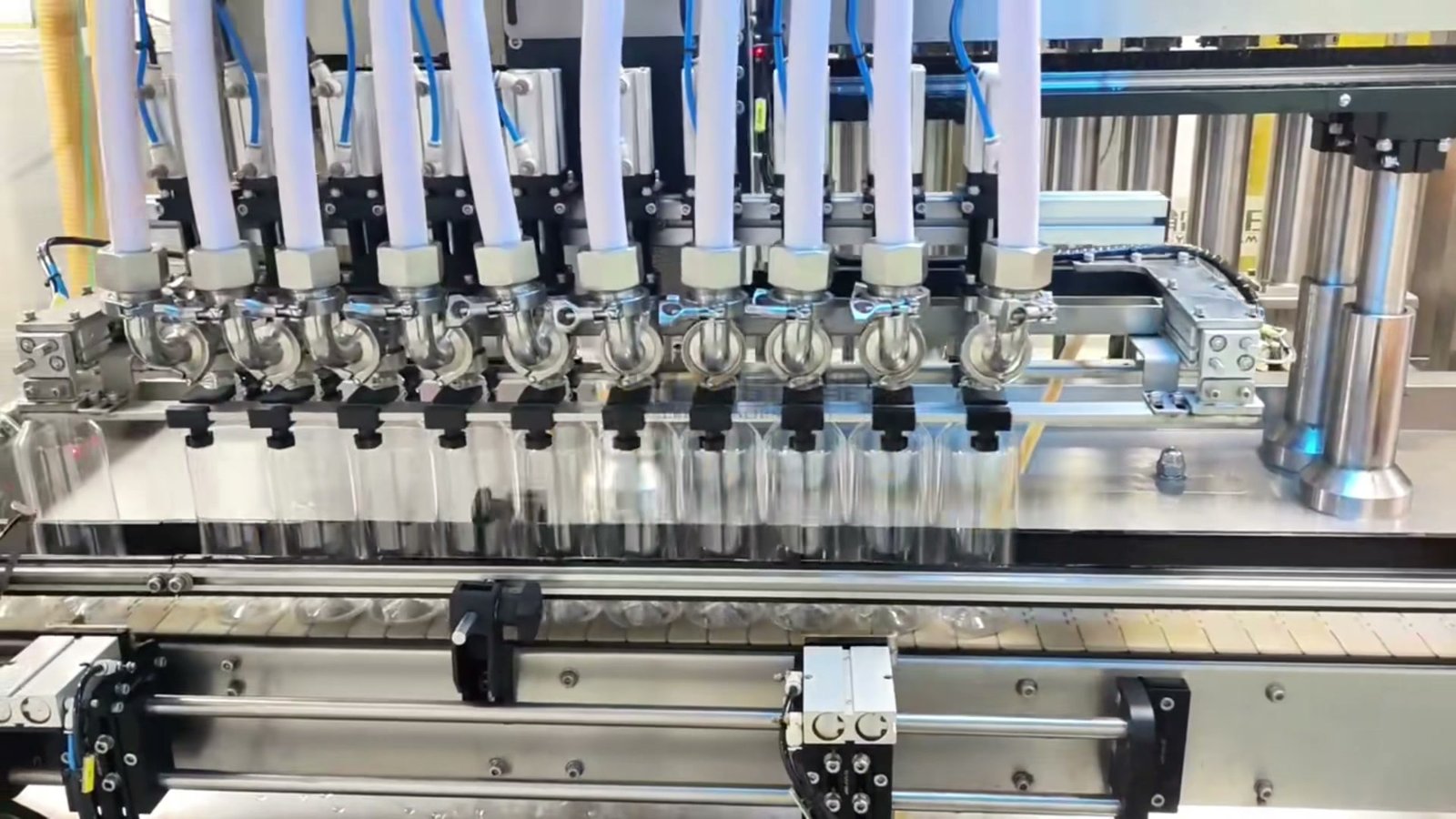
Use these as configuration examples, not interchangeable specifications. LEKA’s complete liquid filling line solutions provide a route to discussing the filling, closing, conveying, and downstream equipment needed for your project.
Frequently Asked Questions
Is an inline filler the opposite of a monoblock?
No. Bottle movement and equipment integration are different questions. Ask the supplier to show the bottle path and identify which operations share the unit, rather than selecting by the label alone.
Which option costs less?
There is no useful universal price winner. Compare quotes with the same cap feeding, format coverage, transfer equipment, controls, testing, and support. Include the cost of retaining or replacing existing equipment.
Will separate machines keep running if the capper stops?
Not necessarily. Continued filling depends on the controls, available safe holding capacity, and what is permitted for open product. Request a demonstrated stop-and-restart sequence instead of assuming separation provides that benefit.
Can an integrated machine handle pumps and triggers?
Some integrated platforms handle specialized closures, but this is model- and format-specific. Require confirmation of feeding, orientation, dip-tube handling, placement, and closing with your samples. A general capping specification is insufficient.
Does tool-less changeover mean no replacement parts?
No. It describes how an adjustment or replacement is performed. Ask which changes are recipe-only, which require hand adjustments, and which need dedicated bottle or cap parts.
What if the final bottle or cap is not ready?
Use drawings and provisional samples for an initial discussion, but identify them as provisional. Agree which design choices and performance commitments remain open until production-intent samples can be tested.
Ask for a Comparison Based on Your Bottles
The right choice is the configuration that meets your production needs with clear responsibilities and convincing sample tests. Start with three items: your product and fill volume, bottle and cap photos or drawings, and required good output. Include physical samples when available.
Also tell LEKA how often formats change, which machines you want to retain, and whether your next package will use a different closure. Layout, utilities, cleaning requirements, and testing details can then refine the proposal.
Send LEKA your product, bottle, and cap details and request a configuration review covering format changes, cap handling, transfer, and acceptance requirements.
Technical Sources
Sources checked September 18, 2026. Other manufacturers’ examples explain design considerations; they are not specifications or performance guarantees for LEKA equipment.
- Tirelli: Sigma monoblock configurations and cap-feeding options.
- Accutek: Mini Monoblock rotary configuration.
- Septimatech: Cap Positioning Challenges case study.
- Nercon: sample-bottle testing for a sanitizer conveyor application.
- Septimatech: machine changeover parts.
- Nercon: accumulation system selection criteria.
- Nercon: accumulation discharge and back-pressure considerations.
- eCFR: 21 CFR 117.40, equipment and utensils.
- PMMI: updated FAT guidance announcement, August 10, 2022.
- CDA: the difference between FAT and SAT, September 26, 2024.