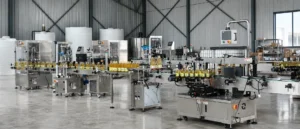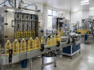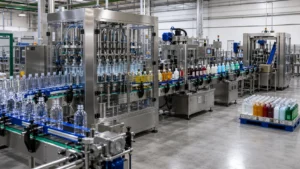
Rotary vs Inline Liquid Filling Machines
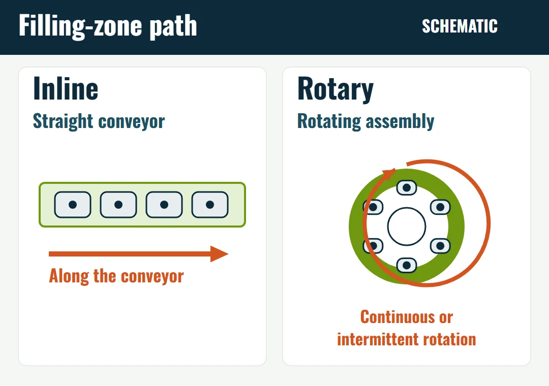
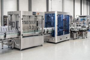
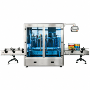
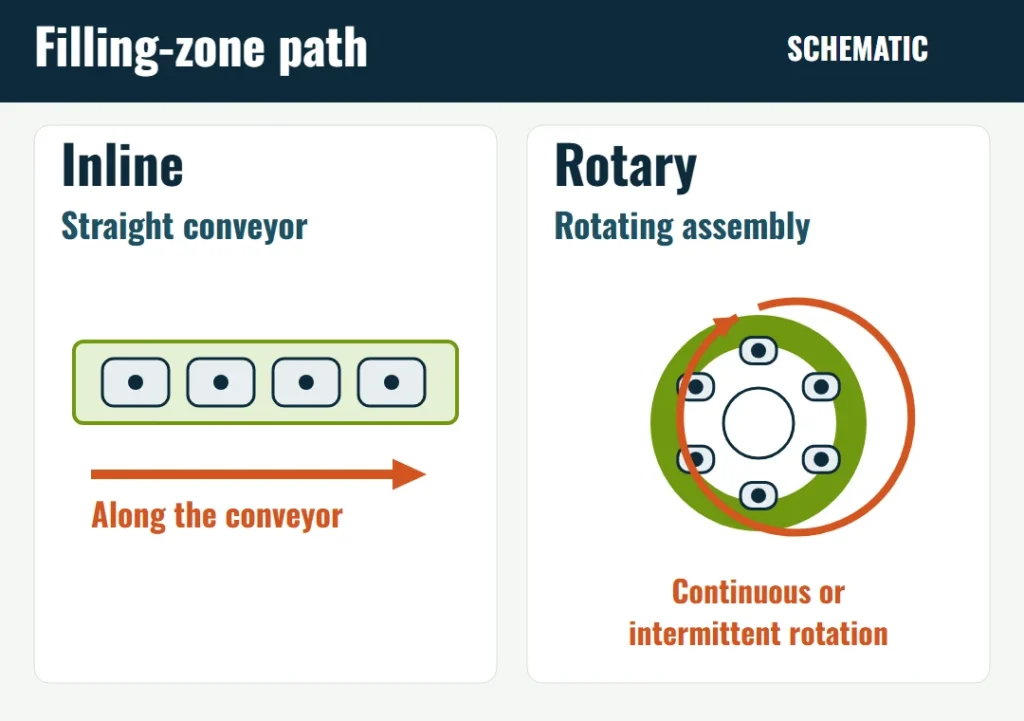
An inline liquid filling machine keeps each bottle on a straight conveyor through the filling zone. A rotary liquid filling machine carries the bottle on a rotating assembly while the dose is delivered. The choice between them is the handling in that filling zone, read together with the full bottle range, the batch pattern, the change parts, the way the product fills, and the target number of accepted bottles.
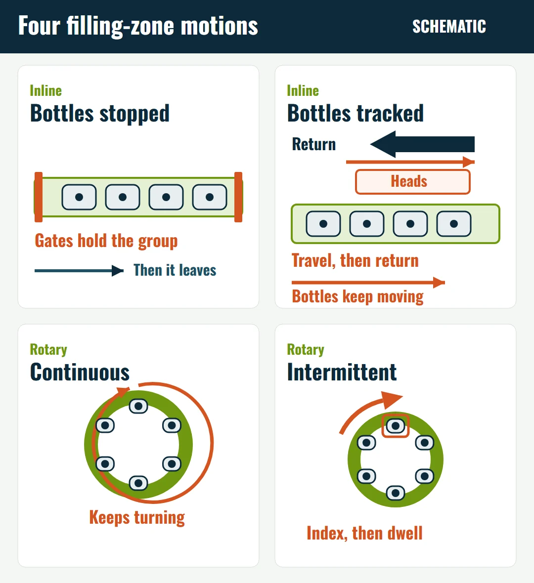
Four filling-zone motions show up on bottled-liquid quotes. An inline machine can stop a group of bottles under the nozzles, or it can keep the bottles moving while the heads travel with them and then return. A rotary machine can keep the assembly turning during the fill, or it can index and let the bottles dwell. The path name does not set the price, the floor area, the changeover, or the output.
Classify the machine by what carries the bottle during the fill. An infeed starwheel that only spaces bottles, or a turntable that only collects them, leaves that classification unchanged. A collection turntable and an unscrambler are feeding or accumulation machines. The drawing should name them on their own.
Four filling-zone motions
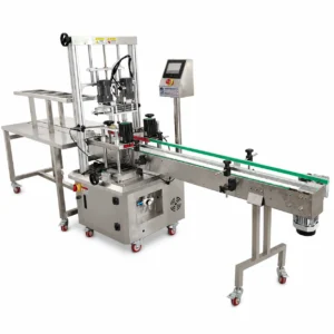
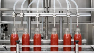
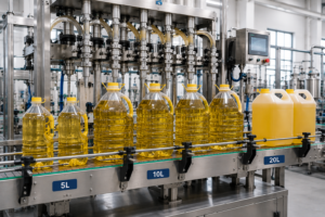
Inline, bottles stopped. The conveyor brings a group of bottles to the nozzles. The bottles are filled while they are stationary, then the group leaves and the next group enters.
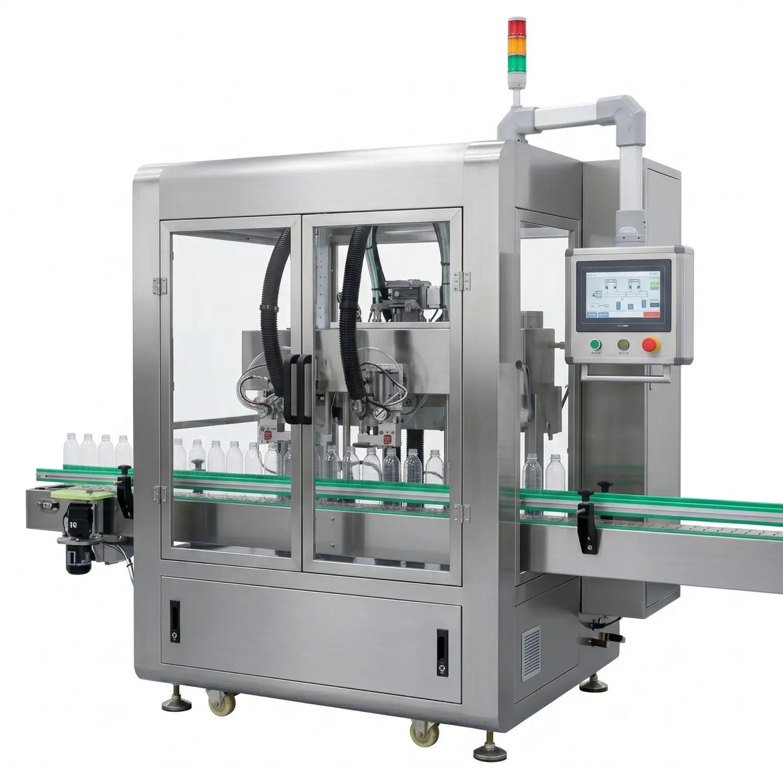
Inline, bottles tracked. The bottles stay on the conveyor and keep moving. The filling heads travel with them for the dose, then return for the next bottles.
Rotary, continuous. A rotating assembly carries the bottles through the filling zone and keeps turning while the dose is delivered.
Rotary, intermittent. The rotating assembly indexes, and the bottles dwell while a station works.
Keep the path, the dose, and the frame apart
The bottle path is separate from the filling principle. Different systems can use time, displacement, flow, weight, or fill level to control the fill.
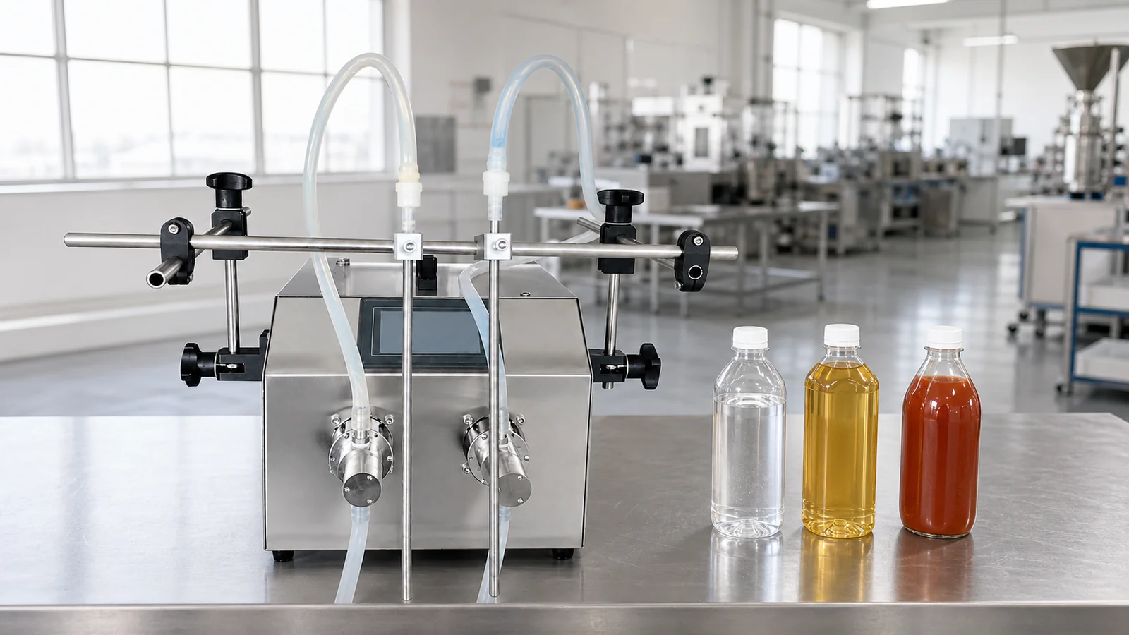
“Rotary pump” does not identify the exact pump design or the bottle path. LEKA’s LEKA-FLDT-ZZB01 specifies a rotary lobe pump and one filling head. The FLSFZ-02-B is described as a rotor-pump tracking filler, with bottles moving along a straight conveyor. These product descriptions do not establish whether the two models use different pump designs.
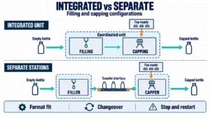
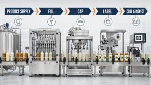
The frame is the third choice. Filling and closing can share one coordinated machine or stand on two machines with a transfer between them. Monoblock filling and capping versus separate machines compares that frame decision. Servo control sits apart again: it can drive a pump, a piston, a nozzle lift, or a tracking carriage. The automatic liquid filling machine guide keeps metering, nozzle movement, and machine format separate. The bottle filling machine guide covers the surrounding line, from bottle supply through capping and labeling.
What to compare on the quote
Swipe to compare both machine types
| Factor | Inline filling zone | Rotary filling zone |
|---|---|---|
| Bottle route | Straight conveyor | Rotating assembly during the fill |
| Motion | Stopped group, or heads that travel with the bottles and return | Continuous turn, or index and dwell |
| Format parts a design may use | Guides, nozzle spacing, gates, tracking pitch, a feed screw | Pockets, clamps, plates, a feed screw, an infeed wheel, a discharge wheel |
| Position signals | A sensor or bottle count can start or confirm the positioning action | A sensor can start or confirm flow into or out of the assembly, where the design uses one |
| Shared frame | Standalone filler, or filling and closing integrated into one coordinated machine. | Standalone filler, or filling and closing integrated into one coordinated machine. |
| Drawing | Conveyor length, operator side, access to nozzles and pumps | Round envelope, infeed and discharge conveyors, access to the rotating parts |
The parts in the format row are pieces a particular design may use. They are not a required kit for every inline or rotary filler. A sensor or a bottle count controls the action. It does not hold the bottle. Gates, a feed screw, a pocket, or a clamp do that holding when the design includes them. A shared frame can use separate handling assemblies for filling and closing.
Use the same checklist on every candidate for cleaning, output, and cost. Those three are covered after the motions, because they follow the quoted hardware rather than the path name.
How the four motions work
Bottles stopped on a straight conveyor
On DTM’s Purefil 1500, adjustable entry and exit gating cylinders are the indexing bottle control. [1]
Cozzoli’s VR2 series uses a straight-line layout. A feed screw positions the containers, and the controls run that timing feedscrew as intermittent container movement. Gating is listed as an option on that sheet, beside a full-length feed screw. A feed screw on a straight conveyor is still inline handling. The VR2 also uses a diving nozzle, with a stated bottom-up travel, and it can be built as a monoblock with stoppering. The feed screw can be set for more than one dose on a large fill or a foamy product. [4]
Bottles tracked on a straight conveyor
On the Purefil 2000 and 2500, the filling heads move with the containers and the fill continues without the stop used on the indexing model. [1] LEKA’s tracking series describes nozzles moving with the bottles, so each bottle does not have to stop at a fixed station. The two-head gear-pump tracking filler and the two-head rotor-pump tracking filler name a gear pump and a rotor pump on those pages. On both, bottles move along the conveyor. For a similar bottle, those LEKA pages describe changes to fill settings, nozzle height, guides, and conveyor position. Another tracking quote can still need a carriage stroke and a pitch that match the bottle spacing.
Continuous rotation
On the CR200/400, containers enter on the infeed conveyor. A timing screw spaces them into starwheel pockets. A larger main starwheel carries them while they are filled. An exit starwheel takes them on for stopper insertion. The sheet calls this continuous-motion handling. The screw, the pockets, and the two starwheels are the parts this model uses. [2]
Intermittent rotation
On the RM, vials can arrive on the infeed conveyor from a turntable or a bulk feeder. The main starwheel then captures them for the processing steps. The machine indexes through the functions that application uses, such as filling and the closing stations, and the vials return to the discharge conveyor. The sheet lists straight-sided round, oval, and rectangular containers inside the maximum diameter given for each frame. Where the machine is equipped for it, the fill can be split into more than one dose. [3]
That container list shows shapes this intermittent monoblock can be built to handle. It does not assign rectangular, oval, or round bottles to one path. An upstream turntable on the same sheet is a way to present vials to the conveyor. The filling-zone handler is the main starwheel. Because this index can include closing as well as filling, a cycle estimate taken from another machine does not carry over to the RM. The filling guide gives a cycle estimate for an indexing filler that completes one full dose per bottle in each cycle, and it says that estimate is not a universal formula for rotary or multi-stage systems.
Nozzle lift is separate from tracking
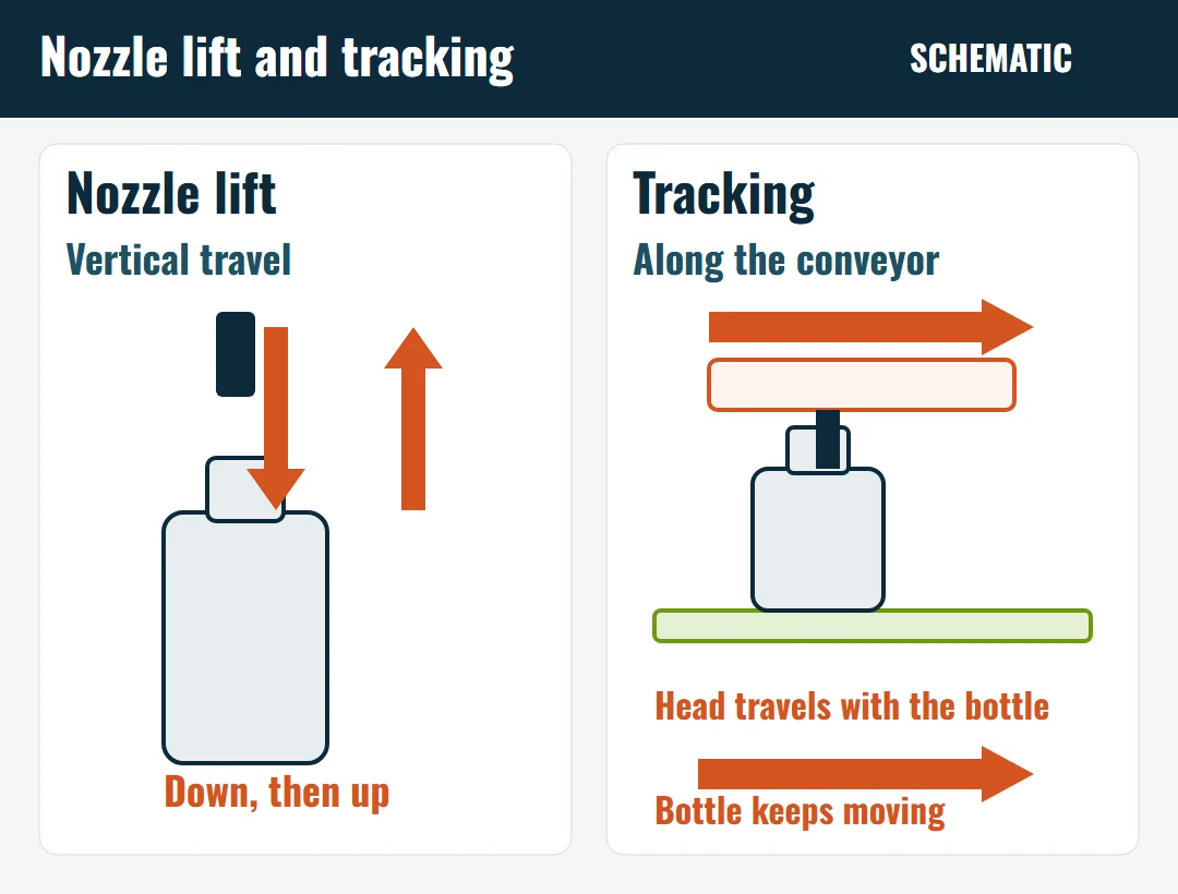
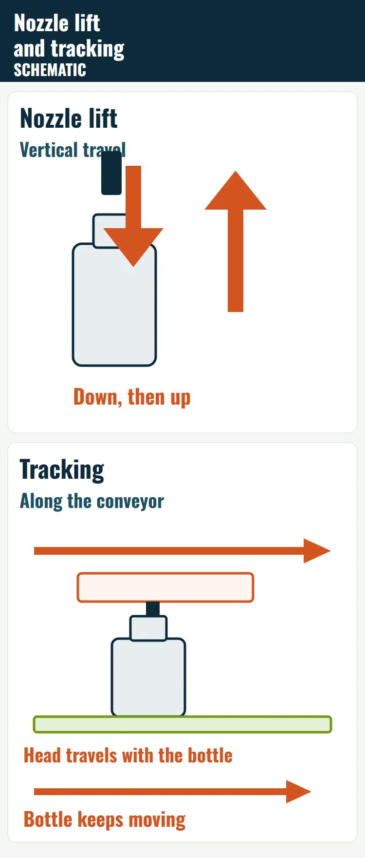
Nozzle action is how the nozzle moves during the dose. Filamatic separates three actions: static nozzles stay in place, locate nozzles enter only a short distance, and bottom-up nozzles lower to a set distance from the bottom of the container, then rise while product is dispensed. Those nozzles are described as driven mechanically, pneumatically, or by servo, with the rise set to stay with the product level and to repeat in timing and placement. Ask the supplier to specify the nozzle stroke, lift profile, and control method for your product. Filamatic pairs bottom-up filling with foaming, splashing, and spilling, and says control of the lift speed can help break the final string on some products. [5]
DTM lists bottom-up fill for foamy or viscous products on indexing and walking-beam Purefil models. On the indexing flow-meter and gear-pump sheets, the nozzle bar’s vertical motion is servo-controlled, for bottom-up or top fill. [1] The VR2 diving nozzle is the straight-line intermittent example above. [4]
Horizontal tracking is the filling head traveling along the conveyor with the bottle. A machine can use vertical nozzle travel, horizontal tracking, or both. If a quoted tracking carriage does not provide the nozzle travel the product needs, that configuration is short of the required nozzle action. Compare the other configurations that provide it.
Compare the candidates on one project
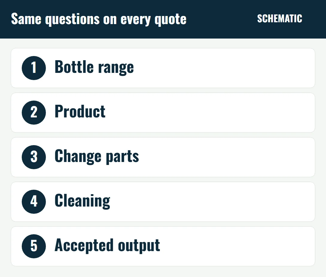
Compare every candidate against the same five inputs: every bottle size and shape, empty and filled; how often bottles and products change; which items are adjustments and which are replaced parts; foam, stringing, viscosity, and particles; and the target accepted output with the basis for that machine.
Bottle stability, a rectangular body, and several bottles being in fill at the same time are each one of those inputs. Several filling heads can dose at the same time on a straight group and on a rotating assembly. None of these facts, on its own, selects the path.
The filling guide points an inline automatic filler toward stable container supply and continuous production. It says a rotary system may be considered for high-volume applications where the product, the container, and the line balance justify it. Select the quote from the product, the bottles, the change parts, and the accepted output.
Frequent size changes. Where the bottles can be guided on a conveyor and the format differences are guides, nozzle spacing, gates, or tracking pitch, that change-part pattern is a reason to include an inline quote. Include a rotary quote on the same bottles, with its pockets, clamps, or plates drawn for every body in the range. Flat sides give guides a face to use. Both quotes stay on the same comparison.
A detergent illustration, not a LEKA installation: rectangular 250 ml, 500 ml, and 1 L bottles, a foaming liquid, and several size changes a week. Ask each supplier for the filling-zone motion, the nozzle action for the foam, the change parts for all three bodies, and the accepted-output basis. Use the 1 L bottle partly filled as one handling check on every candidate.
Many bottles in fill during a long run. Treat the overlap as a capacity input on each quote. Where the project requires the containers to keep moving during the fill, check the quote for that motion: heads traveling with bottles on a conveyor, or a filling assembly that keeps turning. Where the project has not required continuous motion, keep an indexing machine in the comparison. The supplier should name the motion and show how it meets the product, the bottle, and the output.
A still-beverage illustration, not a LEKA installation: one 500 ml round PET bottle, one cap, and a long daily run whose plan depends on many bottles being in fill together. Compare a multi-head inline quote and a rotary quote on that bottle and fill volume. Ask each supplier to name the motion.
Foam, stringing, or a nozzle that has to enter the bottle. Specify the nozzle action on each path already in the comparison. The filling guide treats a diving nozzle as control of entry into the bottle, including foam and splash, and that behavior has to be tested with the product. A tracking configuration without the needed vertical travel is one incomplete option. The comparison then includes the configurations that do provide that travel.
Filling and closing on one frame. Ask for the operations on the shared frame and for the filling-zone motion as two answers. Filling and closing on one coordinated machine can still use separate handling assemblies. LEKA’s FLX-6TSFA combines six-head servo filling with integrated three-claw capping. Monoblock filling and capping versus separate machines compares that shared frame with machines that stand apart. A shared frame still has to feed, orient, place, and close the actual cap.
A cosmetic illustration, not a LEKA installation: bottle height changes often and the cap family stays the same. A taller bottle of the same neck and body points to nozzle height, guide height, and cap-head height. A new neck diameter or body shape adds the guides, pockets, or plates for that body. Sharing a frame does not remove those parts.
Product changes. The clean-out follows the wetted path: supply, dosing unit, valves, hoses, nozzles, and any rotating distributor that design uses. On the DTM sheets cited above, flush-in-place is listed for the indexing models and automated CIP is listed for the walking-beam models. LEKA’s tracking pages describe flushing the pump, hoses, and nozzles, and list clean-in-place as optional. Ask which parts the cycle reaches. Use the filling guide to match piston, pump, flow meter, timed flow, or net weight to the viscosity, particles, and foam, then ask every quote to mark the same parts as in-cycle cleaning or strip-down.
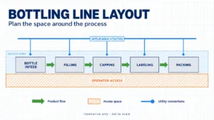
Floor space is the quoted drawing. Bottling line layout is where operator access, service clearance, and utilities are planned. Compare those clearances on the quoted conveyor or the quoted rotating assembly, including the infeed and discharge.
Read the investment and the output on one scope
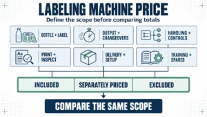
Put the same items on every quote before comparing totals:
- the filler and the dosing method
- format parts, and the adjustments an operator makes without new parts
- cleaning time between the products actually run
- the maintenance points an operator must reach, including guards around a tracking carriage or a rotating assembly
- the conveyor, capper, labeler, and coder connections, and who supplies each connection
Compare those investment and operating costs on the quotes in hand. The path name does not carry a price.
For each quoted output figure, ask the supplier to state the target number of accepted bottles and the calculation basis that fits that machine: stations in the motion, containers completed per index or per pass, one dose or several, and the cycle limits. Name the product, the bottle, and the fill volume. An earlier test on that same product and bottle can be the basis instead. The quotation can use that calculation or that earlier test. It does not have to wait for a test of a machine that has not yet been built. The order then sets the accepted result for the purchased configuration, the samples, and the acceptance conditions. Useful points are accepted bottles at an agreed discharge, the fill-tolerance method, one planned bottle change, one planned product clean-out, and one planned stop and restart. The bottle filling machine output guide explains why the count is taken at the line point you care about. The rate of the whole line follows the slowest stable station.
Questions buyers ask
Does a monoblock mean the bottles travel in a circle?
A monoblock means two or more operations share one coordinated frame. Ask the quote for the filling-zone motion and for the list of operations on that frame. A straight-line machine can include closing. A rotating assembly can be a filler only. The monoblock comparison keeps those two questions apart.
Is a rotary-pump filler a rotary filling machine?
A rotary pump names the pump. A rotary filling machine is defined by how the bottle moves through the filling zone. Pump type and bottle path answer different questions.
The bottles keep moving during the fill. Is the machine rotary?
The machine is rotary when a rotating assembly carries the bottles through the filling zone. Bottles that keep moving on a straight conveyor, with nozzles traveling with them, are on a tracking inline filler. LEKA’s tracking series describes that conveyor motion.
A diving nozzle lowers into the bottle. Is that tracking?
A diving nozzle travels vertically on the lift designed for that fill. Tracking means the filling head travels along the conveyor with the bottle. One machine can use either motion or both, and the quote should name them separately. The filling guide treats the diving nozzle as a nozzle choice to test with products that foam or splash.
Send the details that decide the configuration
Send the liquid and how it flows, the fill volume, the bottle range, the target output, how often you change products or bottles, and the equipment and floor space already in the plant. LEKA will use that information to compare suitable filling configurations.
Request a filling-configuration review
Sources
Read on 4 October 2026. The Cozzoli sheets prove the structure of the named models. They do not establish beverage or detergent performance.
- DTM Packaging, Purefil in-line fillers. Purefil 1500: indexing, bottles stop under the fill heads, entry and exit gating cylinders. Purefil 2000 and 2500: walking beam, heads move with the containers. Bottom-up fill is listed for foamy or viscous products on indexing and walking-beam models. https://dtmpackaging.com/machines/filler/purefil-in-line-fillers/
- Cozzoli Machine Company, CR200/400 data sheet. Continuous-motion vial filling and stoppering. Infeed conveyor, timing screw, starwheel pockets, fill on the main starwheel, exit starwheel for stopper insertion. https://www.cozzoli.com/wp-content/uploads/2019/01/CR-Series.pdf
- Cozzoli Machine Company, RM-series data sheet. Intermittent rotary monoblock. Main starwheel, “Container Movement: Intermittent,” straight-sided round, oval, and rectangular containers within the listed frame diameters, and double or triple dosing where equipped. An infeed turntable on this sheet presents vials to the conveyor. https://www.cozzoli.com/wp-content/uploads/2019/01/RM-Series-Data-Sheet.pdf
- Cozzoli Machine Company, VR2 inline filler data sheet. Straight-line intermittent handling, feed screw, diving nozzle, optional gating, multidose setting, and a stoppering monoblock option. https://www.cozzoli.com/wp-content/uploads/2019/01/VR2InlineFiller-and-VR2PP.pdf
- Filamatic, “Filling Action: Ready… Set… Fill?” Static, bottom-up, and locate nozzle actions. Bottom-up lift is described as a mechanical, pneumatic, or servo motion, with the rise set to stay with the product level and to repeat in timing and placement. https://www.filamatic.com/blog/filling-action-ready-set-fill/