

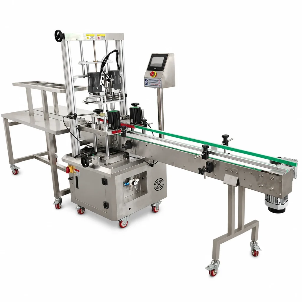
Types of Capping Machines: Spindle, Chuck, and Press-On
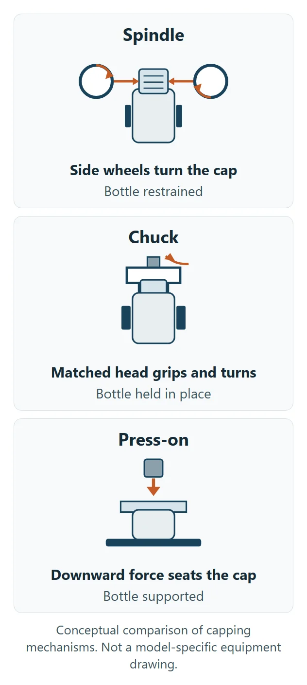
A spindle capper turns a threaded cap with rotating wheels. A chuck capper grips and turns the cap with a matched head. A press-on capper seats a snap-fit or friction-fit closure with downward force. The right mechanism depends on the closing action the cap requires, the surfaces the machine can contact, and how the bottle is supported.
This guide helps factory owners, production managers, and packaging engineers compare these three mechanisms for bottle packaging. Roll-on aluminum closures, crown caps, and corks require other equipment and are outside this comparison.
Spindle, Chuck, and Press-On Capping: Quick Comparison
| Capping Mechanism | Closing Action | Closure Conditions to Review | Bottle Handling Requirements | Checks Before Quotation |
|---|---|---|---|---|
| Spindle | Rotating wheels contact the outside of the cap and turn it as the bottle passes through | Threaded caps with an accessible contact surface | Bottle restraint must allow the cap to turn relative to the neck | Wheel access, cap placement, bottle grip, and changeover requirements |
| Chuck | A matched head grips and turns the closure; some configurations also pick and place the cap | Threaded closures whose shape can be accommodated by the proposed head or insert | The bottle must remain located and restrained while the head turns | Chuck fit, cap transfer, head clearance, tightening control, and any required downward force |
| Press-on | Downward force seats the closure without tightening a thread | Closures designed for snap or friction retention | Bottle support must withstand the closing force without unacceptable deformation | Cap alignment, bottle support, seating, and package-integrity requirements |
The table compares closing mechanisms, not fixed speed or price categories. The proposed machine must be evaluated with the bottle-and-cap combinations you intend to produce.
How Do Mechanism, Cap Type, and Automation Differ?
The mechanism describes how the cap closes. The cap type describes the closure. Automation describes which tasks the machine performs. These are separate selection decisions.
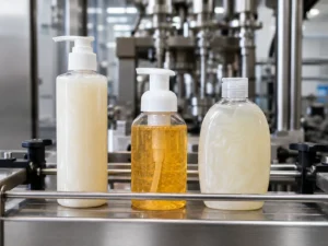
A screw cap may be tightened by wheels or a matched rotating head. A snap-fit cap requires a seating action. A pump or trigger sprayer must be assessed by its actual attachment design, not its product name alone.
Manual, semi-automatic, and automatic arrangements can use the same basic closing action. An automatic project may include cap sorting, transfer, placement, and tightening, but those functions must be identified in the quotation.
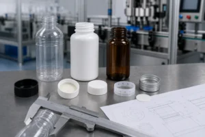
For pumps and trigger sprayers, review dip-tube length and head orientation. For flip-top closures, review hinge orientation and closing-head clearance. Start with the bottle and cap compatibility checklist to confirm the neck finish, closure drawings, sealing components, and representative samples.
What Is a Spindle Capping Machine?
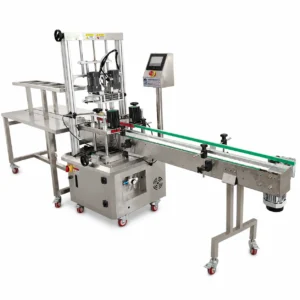
A spindle capping machine uses rotating wheels or discs to transfer rotation to a threaded cap while the bottle passes through the tightening section. The wheels contact the cap’s outside surface, and bottle restraint allows the cap to rotate relative to the neck. Accutek’s capping overview describes this roller-based action and distinguishes manually placed caps from automatic cap-placement configurations.
Spindle capping is a candidate when the wheels can reach a suitable part of the cap without interfering with hinges, spouts, or other features. The bottle shape must also allow stable restraint. Flat, irregular, tapered, or flexible bottles require review of the actual gripping arrangement.
Before choosing a spindle setup, confirm:
- Where the wheels contact the cap and whether that surface is suitable.
- How the bottle is restrained without unacceptable deformation.
- Whether caps arrive already placed or require automatic sorting and transfer.
- Which adjustments or parts are needed for each planned bottle-and-cap format.
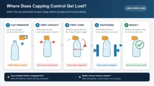
If the bottle rotates with the cap, effective relative rotation is reduced and tightening may fall short. For an existing production fault, use the bottle spinning and cap-placement guide rather than choosing another mechanism from the final defect alone.
What Is a Chuck Capping Machine?
A chuck capping machine uses a matched rotating head to grip the closure and turn it onto the bottle. Some configurations tighten a cap that has already been placed. Other automatic configurations can pick a cap, place it on the bottle, and tighten it. E-PAK’s chuck capper description provides an example of the combined pick, place, and tightening arrangement.
The chuck or insert must suit the closure’s shape and contact surfaces. A chuck approaches the cap from above, but that does not mean every design grips only the top face. Changing the cap may require a different head or insert, a setting change, or both.
A dedicated head may be considered for closures with features that need a particular gripping arrangement. The quotation should show how the proposed head accommodates hinges, spouts, overcaps, or child-resistant features and how the bottle is restrained during rotation.
Check the cap-contact geometry, head clearance, bottle support, tightening control, and cap-transfer method. Some child-resistant closures also require downward force during application; confirm that requirement with the closure supplier and include it in the agreed trial.
What Is a Press-On Capping Machine?
A press-on capping machine seats a closure by applying downward force. The closure is retained by its designed snap or friction fit, rather than by tightening a thread. Accutek’s snap-cap explanation describes the seating action and the need for the container to withstand the applied force.
Press-on capping is a candidate when the cap and neck are designed for this attachment method. The proposed equipment must align the closure and support the bottle during seating. Bottle rigidity, shoulder shape, support position, and directional features all need review.
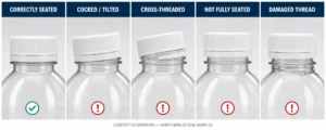
Check full engagement, component damage, bottle deformation, and the package-integrity requirements agreed for that closure. A cocked cap or distorted bottle calls for evaluation of the press-on package and equipment; a continuous-thread troubleshooting procedure should not be assumed to apply.
Changing a torque setting does not convert a screw-tightening mechanism into a press-on mechanism. If a production plan includes both threaded and snap-fit closures, ask which closing components and changeover arrangements the proposed machine provides.
How Do You Choose a Capping Mechanism for Your Bottles?
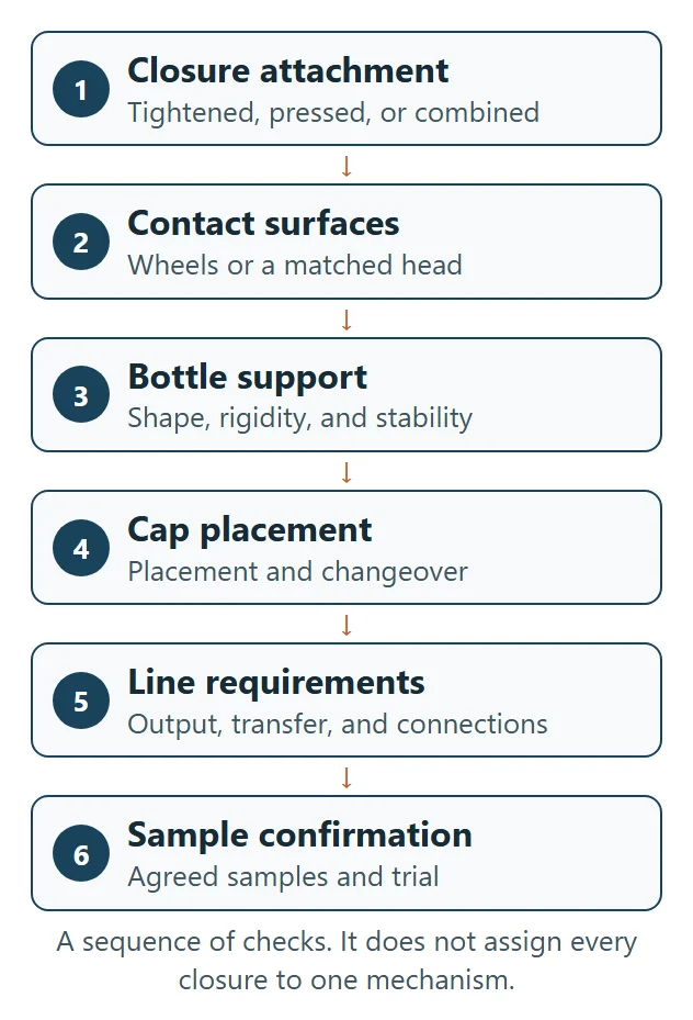
Choose the closing action first, then evaluate cap contact, bottle restraint, cap handling, and line integration. A familiar mechanism name is not enough to select a configuration.
- Confirm the closure design. Establish whether the cap is tightened, pressed into place, or needs a combined action. Use the closure supplier’s drawings and application requirements.
- Review machine contact. Check whether wheels can access the cap or whether a matched head is needed. Include hinges, spouts, tamper features, and required orientation.
- Review bottle support. Assess the bottle in its production condition, including rigidity, shape, and stability during the proposed closing action.
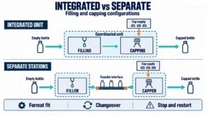
- Specify cap handling and changeover. Identify who or what places the cap and which parts or adjustments change between formats. Pick-and-place describes cap transfer, not a separate tightening mechanism.
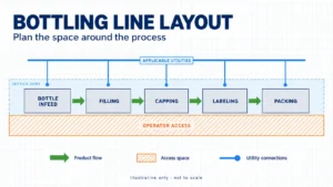
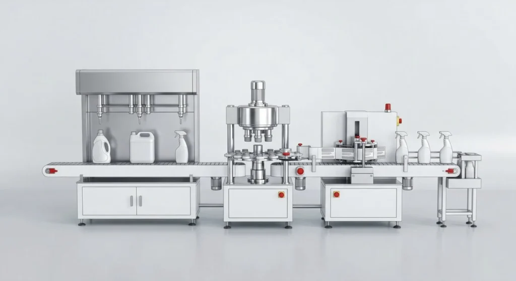
- Match the complete line. Compare the required output, container transfer, conveyor height, access, and connections to filling, sealing, labeling, and packing.
These checks help prepare a quotation. Final suitability should be confirmed under the sample and acceptance conditions agreed for the project.
How Should the Closing Result Be Checked?
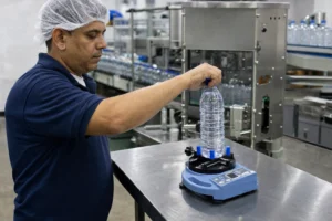
Application torque and removal torque are different measurements. Opening a finished bottle does not reconstruct the torque applied during capping. For threaded closures, use the test event, conditions, and limits agreed by the package owner and closure supplier. The bottle cap torque measurement guide explains how to define and record the relevant measurement.
Check seating, intended thread engagement, and package integrity separately. A torque result does not replace those checks. Press-on closures require checks appropriate to their seating and retention design.
For existing loose, overtightened, or cross-threaded continuous-thread closures, follow the bottle capping problems guide. It addresses fault diagnosis; this article addresses mechanism selection.
Capping Options to Discuss with LEKA
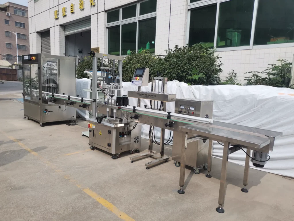
LEKA Pack Line supplies capping equipment and packaging-line configurations matched to the product, bottle, closure, output target, and factory layout. The following equipment can be discussed using its own model name and the actual package samples.
LEKA-CP-A Four-Wheel Screw Capping
LEKA-CP-A uses four capping wheels and side belts for common screw-cap bottle projects. Wheel pressure and position are adjusted for the package, with the final tightening result confirmed using cap samples. Bottle shape, neck finish, cap dimensions, and gripping conditions should be reviewed together.
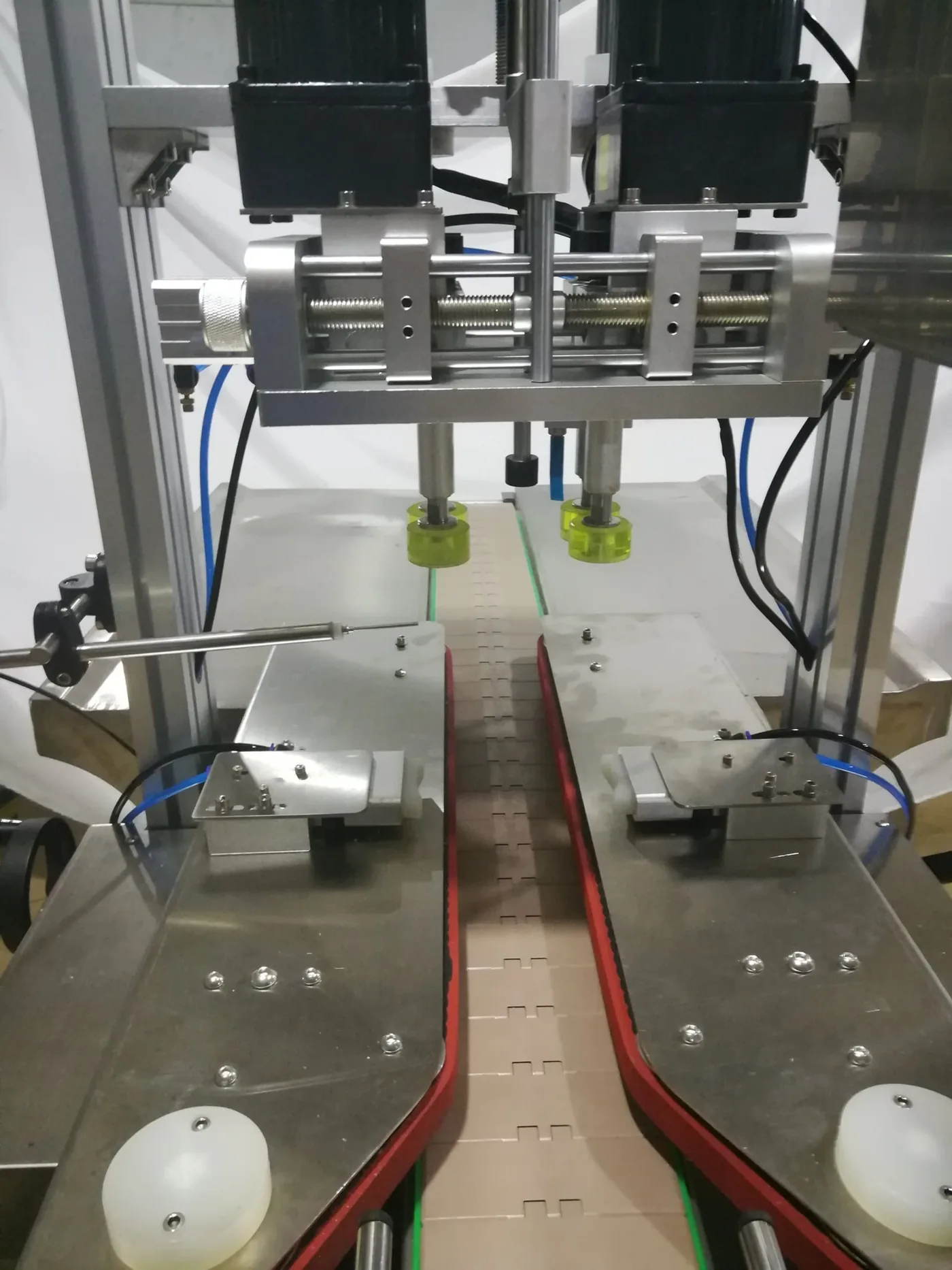
Where bottle-height changes are part of the production plan, LEKA-CP-A-servo adds servo-controlled lifting to the four-wheel arrangement. Discuss the required format range and changeover process before choosing the configuration.
LEKA-CP-B-servo Claw-Type Lock Capping
LEKA-CP-B-servo uses a claw-type locking arrangement with servo lifting. Selected special closures and selected screw-cap projects require sample review of the head, closing action, and bottle support.
For other closing requirements, including press-on caps, send the bottle and closure before selecting equipment. Compare project configurations on the automatic capping machines page.
Frequently Asked Questions
Does a Child-Resistant Cap Require a Separate Mechanism?
Child resistance describes an opening feature, not one universal application mechanism. The cap may require rotation, seating, or combined actions. Confirm the application requirements with the closure supplier and the proposed equipment configuration.
Can One Machine Close Screw Caps and Snap Caps?
Only if the proposed machine includes the components and controls required for both closing actions. Adjusting wheel pressure or a torque setting alone does not provide a press-on function. Include both closure designs in the quotation and test plan.
Does a Faster Catalog Rate Make One Mechanism Better?
A catalog rate alone does not establish suitability. The quotation should identify the target output, machine configuration, bottle-and-cap combinations, and the calculation or test evidence supporting the rate. Final accepted output should be confirmed using the samples, running conditions, and acceptance method agreed by both parties.
Which Guide Applies When Bottles Spin or Caps Are Loose?
Use the placement and gripping guide for bottle movement, cap transfer, and first engagement. Use the capping problems guide for broader continuous-thread closure faults. Mechanism selection should follow the package requirements rather than a defect in isolation.
Request a Capping Configuration
Send your bottle-and-cap combinations, required output, cap-placement method, and factory layout. Include pump or trigger orientation and dip-tube details where applicable. LEKA will review the closing action and line requirements before recommending a suitable configuration. Sample quantities and trial conditions can then be agreed for the project.