Bottling Line Layout: How to Plan Space, Access and Utilities Before You Buy
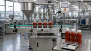
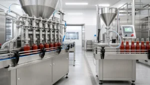
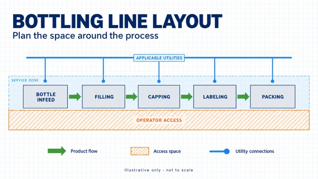
Plan your bottling line layout before buying equipment so you can review how the machines, materials, people and utility connections will share the available space. A machine footprint shows where the equipment stands. It does not show where an operator replaces labels, a technician removes a component or a forklift collects finished pallets.
A useful preliminary layout brings these requirements together. The goal is to give your supplier enough verified information to discuss equipment placement and identify unresolved interfaces before you commit to a configuration.
A Six-Stage Process for a Bottling Line Layout
Use this Six-Stage Layout-Ready RFQ Process to prepare your request for quotation, or RFQ:
- Define the production basis: what the line must package and deliver.
- Survey the usable site envelope, including equipment delivery access.
- Map every flow, from empty bottles to waste removal.
- Define machine interfaces and responsibility for each handoff.
- Overlay access needs and applicable utilities.
- Confirm project requirements and the limits of preliminary review.
This is a planning framework for buyer–supplier discussions. Final engineering requires confirmed equipment data, site verification and review of applicable local requirements.
Stage 1 — Define the Production Basis
Start with the production task. Before arranging machines, prepare a product-and-package record:
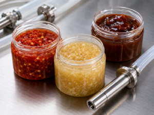
- Product: viscosity at filling temperature, foaming tendency, particles, corrosiveness and relevant handling or sanitation requirements.
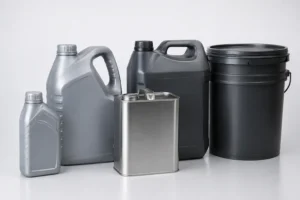
- Package: bottle material, dimensions, neck opening, base stability and fill volume; cap type; label type, dimensions and position.
- Production: required sustained output, shifts, number of SKUs, changeover frequency, cleaning method and automation level.
- Connections: existing upstream and downstream equipment, product-feed arrangement and finished-container discharge requirements.
Sustained output means the production rate you need to maintain under agreed operating conditions. Record the product, format and time basis; do not substitute an advertised maximum speed. Use our filling machine output planning guide for the capacity calculation.
Send bottle and cap samples or confirmed drawings early, with label details. Flag hot filling, flammability, corrosion or hygiene-sensitive processing for specialist review. These conditions may affect materials, handling, access and services; they do not establish equipment suitability by themselves.
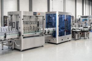
Once the product and package are defined, explore complete liquid filling line solutions for the configuration discussion.
Stage 2 — Survey the Usable Site Envelope
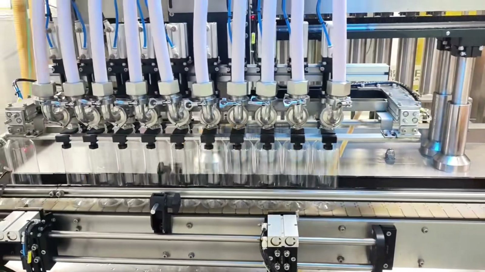
The usable installation envelope is the space available after fixed obstacles, restricted areas and required routes are accounted for. It differs from total building area and from the equipment footprint. Record dimensions with their units, measurement date and drawing revision.
Site Measurement Checklist
| Site Feature | Information to Provide |
|---|---|
| Room and usable space | Wall-to-wall floor dimensions and usable lengths/widths after exclusions; identify the measurement reference points. |
| Overhead limits | Ceiling height and lowest beams, pipes, lights or other obstructions along installation and operating areas. |
| Fixed obstacles | Columns, doors and swing areas, stairs, pits, utility cabinets, fire equipment and fixed machines. |
| Floor and services | Floor condition, level changes, slopes, drains, utility connection locations and known site restrictions. |
| Delivery route | Unloading point, doorway clear width and height, turning points, turning space and overhead restrictions. |
| Installation and expansion | Rigging access, assembly space, restricted zones and the intended direction for later line extension. |
Ask the supplier to check the delivery route against the shipping and installation dimensions. A machine that fits its operating position may still need a different unloading, lifting or assembly plan.
Straight, L-Shaped or U-Shaped?
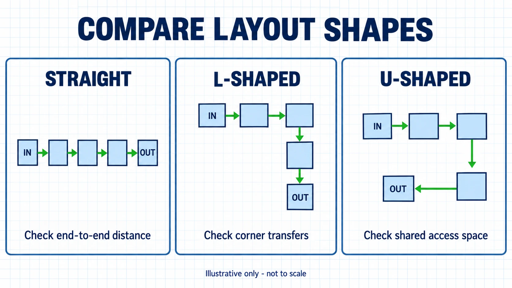
Choose a packaging line layout around actual handoffs and constraints. None of these shapes guarantees higher output or fewer operators.
| Layout Form | Typical Site Situation | Material-Flow Considerations | Access Considerations | Expansion Considerations | Questions to Confirm |
|---|---|---|---|---|---|
| Straight | A clear, elongated area | Check where loading and discharge connect to storage. | Keep both required service sides accessible. | Check available space beyond the line ends. | Can replenishment and pallet removal use practical routes? |
| L-shaped | A corner or offset between process areas | Review container transfer through the turn. | Check access inside the corner. | Identify which leg could extend. | Does the turn avoid an obstacle without creating another conflict? |
| U-shaped | A site where bringing the ends closer may suit workflow | Check incoming and outgoing materials for congestion. | Protect access inside and outside the U. | Check whether either leg can extend. | Can people, replenishment and vehicles remain separated? |
A split or constrained arrangement may be necessary. Record the extra transfer points and responsibilities it creates before accepting the shape.
Stage 3 — Map Every Flow
Do not stop at a conveyor centerline. For packaging line design, use a six-layer map: equipment; containers and materials; people; maintenance; forklifts and logistics; utilities. Mark crossings and blocked access when the layers are combined.
- Containers and product: empty container infeed, product flow to the filler and filled-container discharge.
- Replenishment: cap flow, labels, cartons and other packaging materials, including their temporary staging positions.
- Discharge: finished goods, reject collection and waste removal; show where each stream goes.
- People: operator movement, pedestrian routes, cleaning tasks and maintenance movement.
- Logistics: forklift routes, pallet movement, storage access and loading areas.
Walk through a normal replenishment task on the drawing. Can someone bring a label roll to the labeler while another person removes a reject bin? Does a waiting pallet block either route?
For applicable US workplaces, OSHA 1910.176(a) addresses safe clearances for mechanical handling and keeping aisles and passageways unobstructed. The specific route dimensions require site review. Equipment can fit on paper while these movements still conflict.
Stage 4 — Define Machine Interfaces
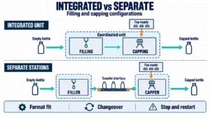
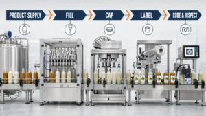
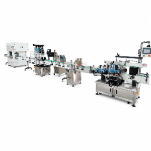
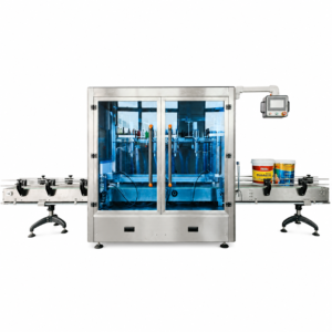
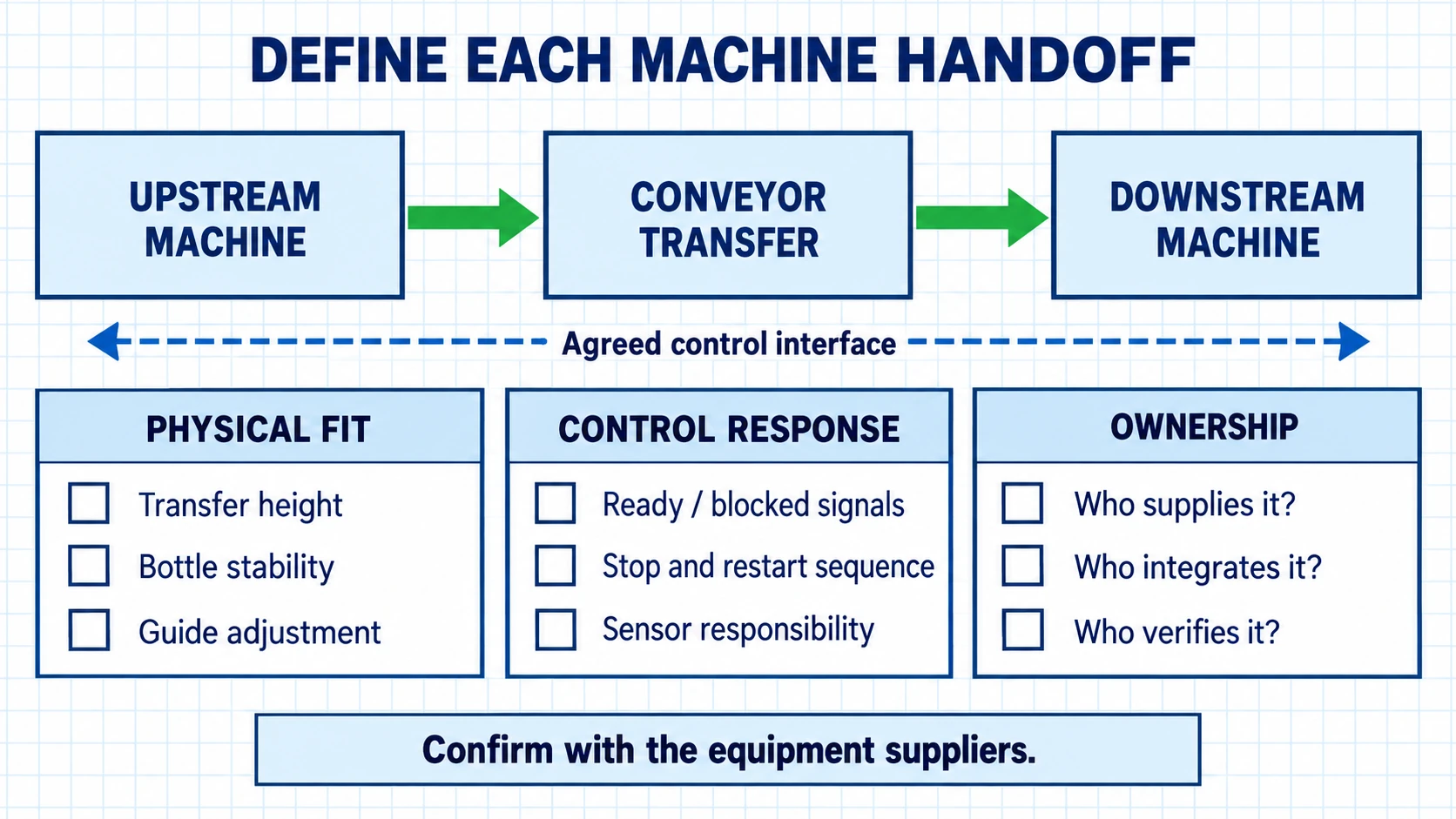
A machine interface is the agreed handoff between two pieces of equipment: container condition, physical transfer, control interaction and responsibility. Use the equipment sequence in our bottle packaging line solutions as a starting point, then document each actual connection.
Machine Interface Record
Copy this record for each equipment pair. Replace prompts with confirmed information and identify unresolved items.
| Machine Interface | Information to Provide |
|---|---|
| Equipment | Sending machine, receiving machine, supplier and drawing revision. |
| Incoming Container Condition | Empty or filled; capped or uncapped; orientation, spacing and stability. |
| Outgoing Container Condition | Condition and spacing required at the next machine. |
| Supported Bottle Range | All formats, dimensions, filled weights and required change parts. |
| Conveyor Direction and Height | Travel arrow and agreed transfer elevations. |
| Transfer Point | Location, transfer method and bottle-support arrangement. |
| Control Interaction | Control handshakes: signals coordinating ready, stop/start, blocked and starved conditions; restart expectations. |
| Reject Handling | Detection, removal, collection and response when collection is unavailable. |
| Upstream and Downstream Dependency | What happens when either machine stops; required accumulation or recovery logic. |
| Access Requirement | Operator, changeover, cleaning, isolation and major-service access. |
| Utility Requirement | Services, connection points and isolation arrangements to confirm. |
| Supplier Responsibility | Who supplies, connects, documents and tests each mechanical and control interface. |
Matching advertised speeds is insufficient. Suppliers must agree how the connected machines respond when bottles stop arriving or cannot leave.
Treat Accumulation as a Recovery Question
Bottle accumulation is temporary holding between operations. Before allocating space, ask which short stop it should accommodate, how long that interruption lasts, and whether the containers can queue without damage or instability.
Then confirm the upstream response, downstream restart and how the queue will clear while meeting the sustained-output requirement. Buffering may accommodate a defined interruption; it does not correct every recurring fault or capacity mismatch. Record the recovery requirement in the interface record. Do not choose conveyor length from peak speed alone or assume that more accumulation will improve overall equipment effectiveness.
Stage 5 — Overlay Access and Utilities
Draw task areas before routing services through them. Review both operating conditions and stopped-machine work before freezing the layout.
Protect Four Types of Access
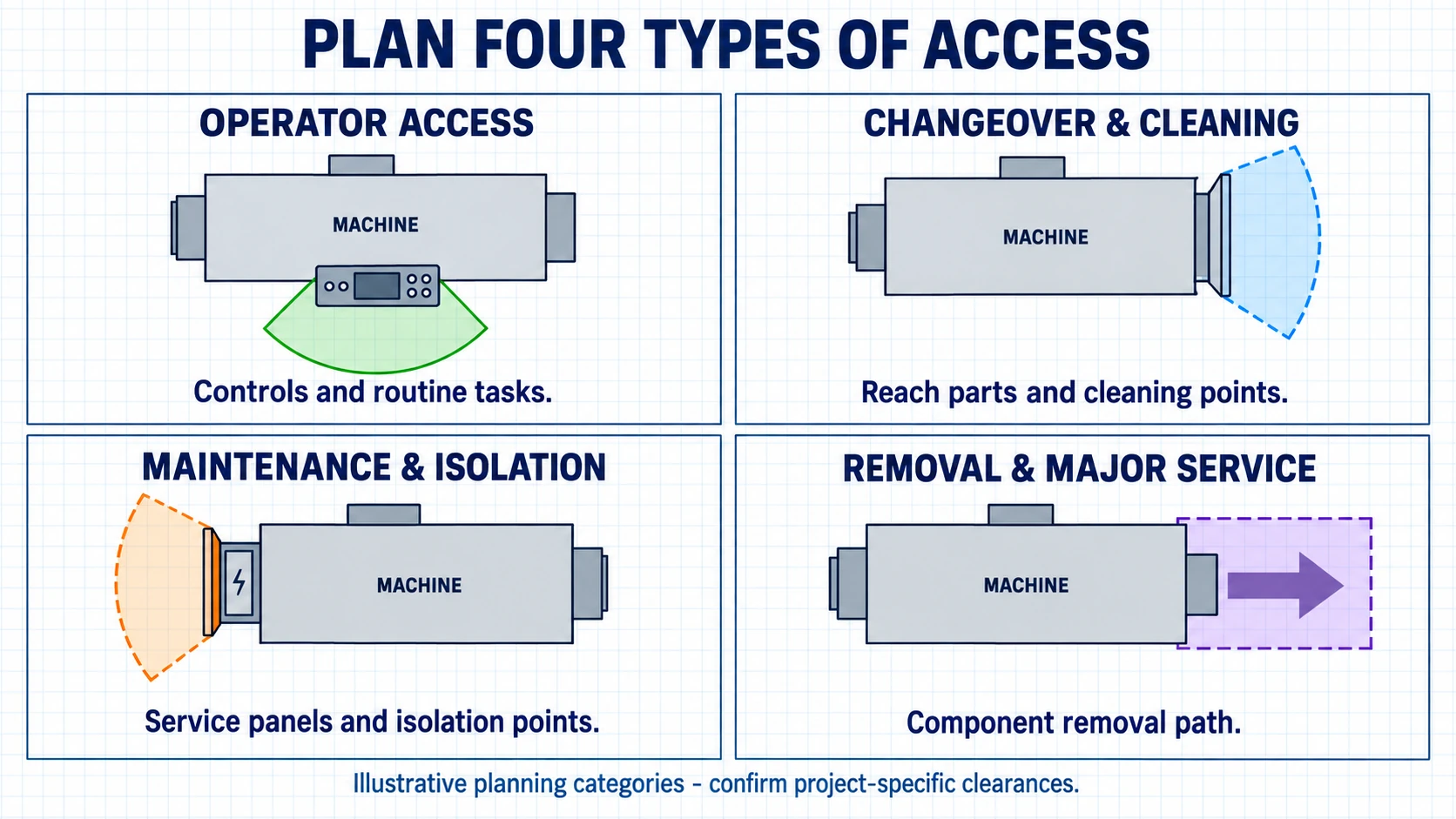
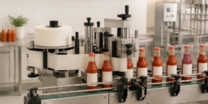
- Operator access: controls, routine inspection, cap feeding, label roll replacement and packaging material replenishment.
- Changeover and cleaning access: format adjustments, guard openings, removable parts, cleaning tools and waste collection.
- Maintenance and energy-isolation access: service points, electrical cabinets and devices used to isolate hazardous energy.
- Equipment removal or major-service access: component withdrawal, lifting arrangements and a clear removal path.
These are this guide’s planning categories, not an OSHA four-zone model. Obtain the required maintenance clearance from equipment documentation and project review.
For applicable US work, OSHA 1910.147 addresses hazardous-energy control during servicing; OSHA 1910.303 addresses electrical access and working space. Confirm isolation access and electrical clearances against the actual installation rather than applying one generic distance.
Utility Applicability Matrix
For each machine, mark every service Required, Not Required or To Be Confirmed. Record who will confirm it. An unknown requirement is not an available service.
| Utility or Site Requirement | Applicability | Information to Confirm |
|---|---|---|
| Electrical supply | To Be Confirmed | Voltage, phase, frequency, load, connection location and isolation. |
| Compressed air | To Be Confirmed | Required pressure, flow, quality and connection; available site supply. |
| Product feed | To Be Confirmed | Source, route, connection, feed conditions and cleaning arrangement. |
| Water | To Be Confirmed | Whether the process or cleaning method requires it; required quality and supply. |
| Drainage | To Be Confirmed | Whether needed; discharge type, route, capacity and local disposal requirements. |
| Data/network | To Be Confirmed | Whether machine communication or reporting requires a connection. |
| Extraction or ventilation | To Be Confirmed | Whether product, process or site assessment calls for it. |
| Temperature control | To Be Confirmed | Whether heating or cooling is required; equipment and service boundaries. |
| Hazardous-area requirements | To Be Confirmed | Whether classification review is needed; qualified reviewer and resulting equipment requirements. |
Do not assume every filling line needs water, drainage or clean-in-place equipment. For applicable US workplaces, OSHA 1910.22 addresses orderly surfaces, feasible dryness and wet-process conditions. FDA’s Part 117 guide describes cleaning, maintenance and contamination-prevention provisions for covered food facilities. Neither provides a universal utility schedule for every bottling project.
Stage 6 — Confirm the Project Requirements
Turn the drawing into a reviewable package. A bottle filling line layout needs agreed inputs and named responsibility for open questions.
Layout-Ready RFQ Checklist
- Product: name, viscosity, filling temperature, foaming, particles, corrosiveness and relevant safety/cleaning information.
- Packaging: bottle drawings or samples, dimensions and material; cap drawings or samples and cap type; label type/details; fill volume.
- Production: target sustained output, number of shifts, SKU count, changeover frequency, acceptable format-changeover approach and cleaning method.
- Site: measured floor plan, usable dimensions, ceiling height, columns, obstacles, restricted areas and equipment delivery/installation route.
- Utilities: available electrical supply and compressed air, product-feed arrangement, drainage information if applicable, and other services marked by applicability.
- Integration: existing machines, interface records, required automation level, manual tasks and supplier responsibility boundaries.
- Project: country, electrical standard, local site limitations, delivery schedule, budget range and intended expansion.
- Acceptance and support: factory acceptance test (FAT) expectations; site verification, installation and commissioning responsibilities; required training, documentation and after-sales support.
Assign an owner and confirmation point to missing information. For expansion, identify the likely additional module and ask whether space, service capacity and interfaces can be reserved.
What a Preliminary Layout Can—and Cannot—Confirm
A preliminary layout supports discussion of equipment sequence, approximate placement, main flow direction, access needs, machine interfaces and utility connection planning.
It does not replace site verification, local code review, final engineering, safety validation, installation drawings or utility engineering. Confirm the final arrangement against the actual products, containers, equipment and site. FAT expectations should be agreed in the project scope; factory testing does not replace site-specific installation and commissioning checks.
Frequently Asked Questions
How much space does a bottling line need?
It depends on the equipment, package, output and site. Include operating, cleaning, maintenance, removal, material and utility space alongside the machine footprints.
Which bottling line layout is better: straight, L-shaped or U-shaped?
Choose the shape that fits the usable space and actual flows while preserving access and expansion options. No shape is universally better.
What information should I send for a bottling line layout?
Send product details, package samples or drawings, sustained-output requirements, a measured floor plan, utilities and existing-equipment information. Flag anything still unconfirmed.
How should maintenance access be planned around packaging machines?
Use the service tasks and supplier drawings to identify access sides, isolation points, panel openings and component-removal paths. Confirm dimensions through project review.
What utilities may a bottle filling line require?
Assess power, compressed air and product feed, then determine whether water, drainage, networking, ventilation or temperature-control services apply to the chosen process.
How do I connect machines from different suppliers?
Agree physical transfers, container conditions, control signals, stop/restart behavior and reject handling. Assign an integration owner and define interface testing responsibilities.
How much conveyor accumulation does a bottling line need?
There is no universal amount. Review the stoppage to accommodate, recovery behavior, container stability and sustained-output target before specifying accumulation.
Can a supplier prepare a final layout from a floor plan alone?
No. A floor plan supports preliminary placement, but final design also needs confirmed process, package, equipment, utilities, access and site requirements.
Prepare Your Layout Review With LEKA
A useful bottling line layout starts with measured space, defined production requirements and clear handoffs. Use the RFQ checklist to bring those inputs together before buying equipment.
LEKA Pack Line can discuss preliminary equipment configuration and layout using your project data. Include utility conditions, existing equipment and the automation level you need. Final suitability remains subject to site, container, product, utility and local-requirement confirmation.
Sources
- OSHA 1910.176 — Handling materials: general, paragraph (a).
- OSHA 1910.22 — General requirements for walking-working surfaces, paragraph (a).
- OSHA 1910.147 — Control of hazardous energy.
- OSHA 1910.303 — General electrical requirements.
- FDA — Part 117 Small Entity Compliance Guide, plant design, sanitary operations, facilities and equipment sections. This nonbinding guide explains requirements for applicable food facilities.