Vacuum Liquid Filling Machine: Working Principle and Bottle Fit
A vacuum liquid filling machine uses a pressure difference to move liquid into a bottle. In the sealed-bottle level-filling configuration explained here, air is removed through one passage while liquid enters through another. The extraction opening helps establish the fill height; a collection vessel intercepts excess liquid before the vacuum source.
For a buyer, the important questions are whether the bottle can hold its shape, whether the product suits the flow path, and whether the priority is a visible fill level or a measured dose. This guide explains those decisions and compares two specific filling arrangements.
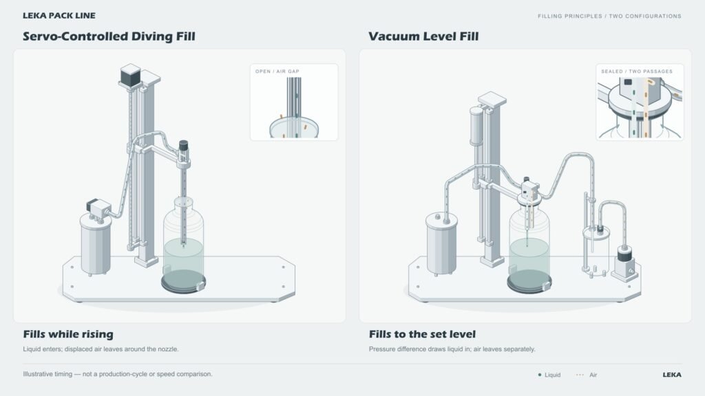
Watch the two filling configurations
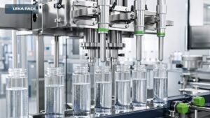
Left: an upstream unit meters the liquid, while a servo mechanism positions the diving nozzle. Right: a sealed head uses a pressure difference to fill toward a set liquid level. Servo positioning and vacuum filling can also be combined in other designs; they are not mutually exclusive technologies.
Read the English video transcript
Two filling configurations, with different stopping controls. The left nozzle dives. The right head seals the bottle. Left: metered liquid enters as the nozzle rises. Air escapes around it. Right: air extraction creates a pressure difference. Liquid enters through a separate passage. Dose stops left flow; right collects excess. Supply stops; pressure equalizes before withdrawal. Metered supply and controlled lift. Pressure-driven filling and level control.
How does vacuum level filling work?
The head seals, air leaves, and liquid enters through an independent passage. In the illustrated arrangement, the head stays at the sealing position during filling. The vacuum source removes gas; it is not a product-transfer pump.
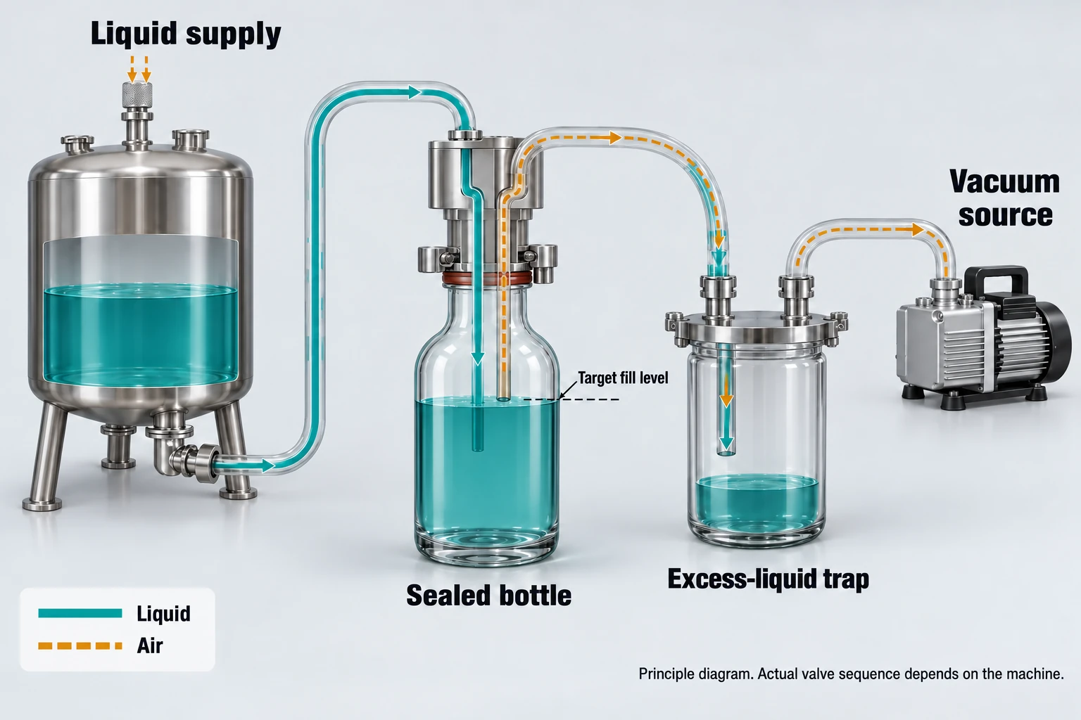
- Position and seal the bottle. The head descends until its gasket contacts the bottle mouth. The seal allows the pressure inside the bottle to be reduced.
- Extract air. Air travels from the bottle through the extraction passage, then through the collection vessel toward the vacuum source.
- Admit liquid. With the product valve open, the pressure difference between the supply side and bottle drives liquid through the separate inlet. Air continues leaving through the extraction path.
- Establish the level. When liquid reaches the extraction opening, a small amount enters the recovery passage. The collection vessel retains this liquid. Reaching the opening establishes the level-control condition; it does not mean every valve must instantly close.
- End the cycle and release the bottle. In this demonstration, the product valve closes, the vacuum path is isolated, and air is admitted to equalize pressure before the head withdraws. The exact valve sequence must match the selected machine design.
The supply circuit and extraction circuit meet inside the bottle, but remain separate passages through the head. Recovered liquid is not shown flowing into the vacuum pump or returning untreated to the product supply.
For a commercial example of the level-control principle, Universal Filling describes its Vacufill as filling rigid containers to a height measured from the bottle neck rather than to a preset volume. Its specifications apply to that machine, not to the animation or a LEKA quotation. Read the Vacufill manufacturer data sheet.
Vacuum level filling or metered diving fill: what changes?
Level control answers “where should the liquid surface finish?” Dose control answers “how much liquid should be delivered?” Equal liquid heights do not guarantee equal volumes when bottle capacities differ. Nozzle lift is a separate positioning function.
| Operating detail | Metered supply + servo diving nozzle | Sealed-bottle vacuum level fill |
|---|---|---|
| Bottle mouth | Open clearance around the filling tube | Gasket seals against the bottle mouth |
| Liquid delivery | Upstream supply unit delivers and meters the dose | Pressure difference drives liquid through a separate inlet |
| Air exit | Displaced air leaves through the open mouth clearance | Air leaves through the extraction passage toward the vacuum system |
| Head movement | Nozzle rises with the liquid surface, keeping a small drop distance in this setup | Head remains in its sealing position during filling |
| Completion control | Set dose is reached; the product valve cuts off flow | Target level is established with excess-liquid recovery, followed by the controlled shutdown sequence |
| Selection priority | Delivered quantity and nozzle-motion requirements | Visible fill height and bottle suitability for the pressure difference |
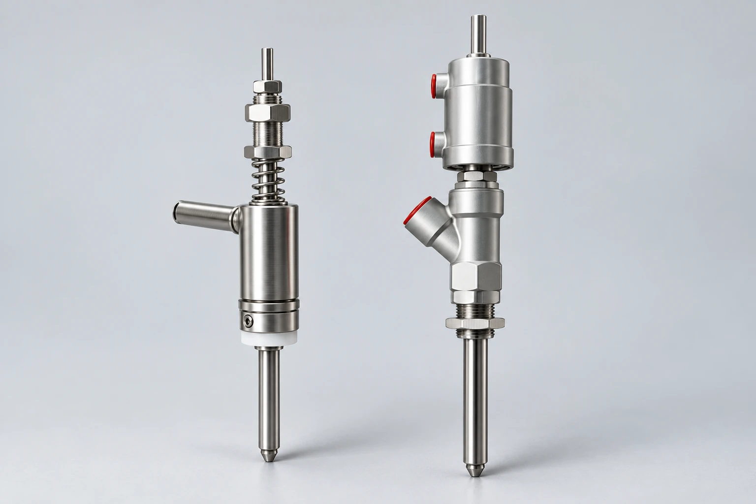
Neither arrangement is automatically faster, more accurate or foam-free. Assess the complete supply, nozzle and control system with the actual product. For other dosing options, see the liquid filling machine selection guide.
Why can thin-wall bottles deform during vacuum filling?
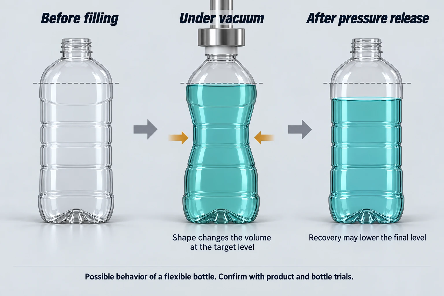
A flexible bottle may bend inward when external air pressure exceeds the pressure inside it. Thin walls can increase this risk, but wall thickness alone is not a pass-or-fail specification. Material stiffness, bottle geometry, reinforcement, temperature and the applied pressure difference all affect how the container responds.
This is a relevant selection concern: ZONESUN identifies flexible plastic bottles as requiring evaluation because they may deform under negative pressure, and recommends testing bottle samples. See the manufacturer’s container-compatibility guidance.
How deformation can affect the final fill
The following is an engineering explanation of a possible failure mechanism, not a measured result for a LEKA machine:
- The wall moves inward. This can reduce the internal space below the target liquid level.
- The target height is reached with less liquid. A level-controlled cycle may therefore reach its set height before the intended quantity has entered.
- The bottle recovers after pressure release. If filling has stopped and the bottle expands back toward its original shape, the same liquid occupies a larger container space and the visible level can fall.
- Different bottles may recover differently. Variation in deformation can contribute to inconsistent final levels or delivered quantities. If deformation also disturbs the mouth seal, the filling process may become unstable.
Practical conclusion: a thin, easily deformable bottle is a poor candidate for this sealed-bottle vacuum configuration unless trials establish acceptable behavior. Do not assume all plastic bottles are unsuitable, or that every glass bottle is automatically qualified. Bottle strength, mouth condition and sealing fit still need confirmation.
What should a bottle trial check?
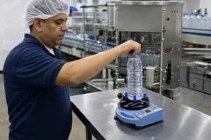
Use the intended liquid at the intended filling temperature and evaluate bottles from representative production batches. Check wall movement while vacuum is applied, seal stability, the final liquid level after pressure equalization, and the delivered mass or volume using an appropriate measurement method. Agree acceptance limits before the trial. Use our filling machine RFQ and factory acceptance checklist to define the test conditions and the evidence required from the supplier. If the bottle changes shape unacceptably, review the container or evaluate a metered configuration that does not require vacuum inside the bottle.
Which liquids and containers should be evaluated?
Free-flowing liquids in rigid, sealable bottles are a useful starting point for evaluating this type of vacuum filler. KBW lists perfume, wine, spirits and other liquids for its AF 0005 vacuum machine, with rigid glass or plastic containers. This supports an application starting point, not universal compatibility across all formulas and machines. See KBW’s vacuum filling machine description.
For perfume and fragrance projects, check volatility, material compatibility, foaming behavior, bottle-neck access and closure requirements. A product name such as “essential oil” or “body mist” is not enough to select the machine. Share the actual formulation characteristics and handling requirements. To plan closure placement, labeling and downstream handling, review our cosmetics and personal care packaging line solutions; the filling method still requires product and bottle assessment.
High viscosity, suspended particles, carbonation or a bottle mouth that cannot seal reliably require a separate configuration assessment. The animation uses one clear, low-viscosity, particle-free demonstration liquid in glass bottles; it does not validate these other applications.
What should you provide before requesting a filling line quote?
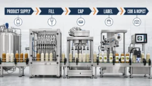
Send the product, container and production requirements together. A nozzle decision affects supply handling, cleaning, closure placement and the rest of the packaging line.
- Product: viscosity at filling temperature, foaming behavior, particles, corrosiveness, volatility and cleaning requirements.
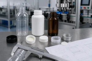
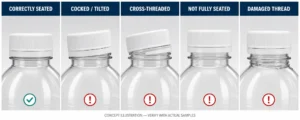
- Bottle: material, drawing or samples, neck finish, opening size, dimensional tolerances and observed flexibility.
- Fill requirement: target quantity, visible level, acceptable variation and how acceptance will be measured after filling.
- Recovery and cleaning: collection-vessel capacity controls, protection against liquid carryover toward the vacuum source, cleaning access and the approved treatment or disposal of recovered product. Recovery does not automatically authorize reuse.
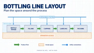
- Line requirements: required output, bottle range, closure or pump type, labeling, coding, available floor space, utilities and automation level.
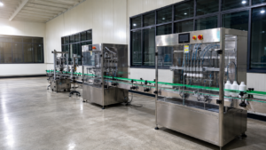
For material selection, review wetted parts for filling lines. For connected equipment, explore complete liquid filling line solutions. Vacuum filling configurations are available for project assessment; the final proposal should identify the selected equipment, trial conditions and integration scope.
Frequently asked questions
Can a vacuum filling machine fill plastic bottles?
Potentially, if the bottle maintains its shape and seal under the intended operating conditions. “Plastic” alone does not establish suitability. Flexible containers need sample trials, including checks after pressure equalization.
Does the same fill level mean the same liquid volume?
No. Different internal bottle capacities can produce different volumes at the same height. If delivered quantity is the primary requirement, evaluate a suitable metering method and verify the finished fill independently.
Does liquid reaching the extraction opening stop everything immediately?
No. In the illustrated arrangement, it starts excess-liquid recovery at the selected height. Product shutoff, vacuum isolation and pressure release are controlled parts of the completion sequence.
Does the vacuum pump handle the product?
The vacuum source removes air through the extraction circuit. The collection vessel sits between the bottle and vacuum source to intercept carried-over liquid. Liquid carryover protection must suit the actual installation.
Is vacuum filling the same as degassing or vacuum sealing?
No. Removing air from the bottle to drive filling does not by itself establish product degassing. The bottle is released after pressure equalization; sealing the final package is a separate operation.
Discuss your product and bottle with LEKA Pack Line
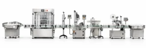
LEKA Pack Line helps buyers plan filling, capping, labeling, coding and conveying equipment around their products and containers. Send bottle samples or drawings, product details, target fill quantity and level, required output and your available space. We can review the filling approach and its connection to the rest of your line. You can also explore our liquid filling equipment options before discussing a specific configuration.
Technical scope: this article explains selected configurations and a possible bottle-deformation mechanism. The animation is an educational illustration, not a machine acceptance test. Final suitability and performance require the agreed product, container and equipment trials.