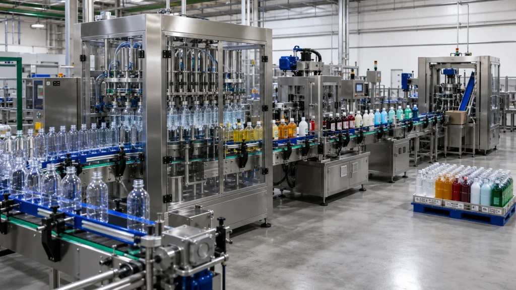
How to Choose an Automatic Liquid Filling Machine for Your Product
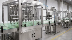
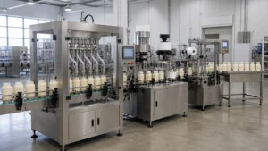
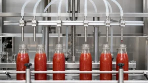
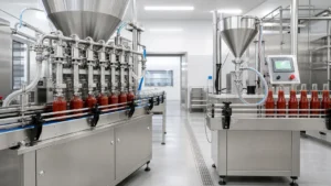
An automatic liquid filling machine dispenses a controlled quantity of product into containers while coordinating the filling cycle with container handling. Choosing one starts with your product and bottle, not the number of heads. This guide helps factory owners, production engineers, and procurement teams compare configurations before requesting equipment from LEKA Pack Line.
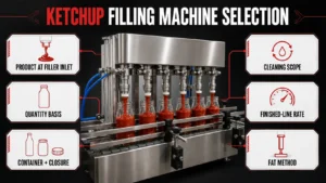
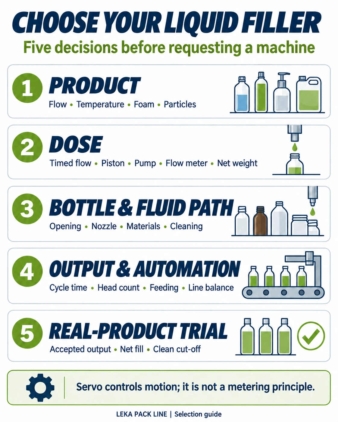
How to choose: define the product's behavior at filling temperature, the container, fill quantity, required output, cleaning needs, and downstream equipment. Then work through these five decisions:
- Characterize the product: record viscosity, foam, stringing, particles, separation, and chemical compatibility.
- Select how the dose is measured: compare timed flow, piston displacement, pump-based dosing, flow-meter measurement, or net weighing against the real product.
- Match the fluid path and bottle: confirm nozzle function, opening size, container support, wetted materials, and cleaning access.
- Size the operating system: calculate the cycle, then check product supply, head count, automation, changeover, and line balance.
- Agree on a real-product trial: define the output measurement window, fill-tolerance sampling, clean cut-off, and cleaning acceptance criteria.
Keep the engineering choices separate: the metering principle measures the dose; machine format describes the station arrangement; servo controls motion; a diving nozzle controls entry into the bottle; contact materials, cleaning, and line integration address other requirements. A water-test speed alone cannot establish performance with your sauce, detergent, oil, or paste.
1. Evaluate Your Product Before Choosing a Filling Machine
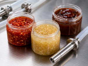
The same product name can describe very different filling behavior. Two sauces may have different particle sizes, temperatures, shear sensitivity, and tendency to separate. Two detergents may differ in foam generation and chemical compatibility. Record how the product behaves during filling, not only the viscosity stated on a data sheet.
Check flow behavior at the filling temperature
Viscosity should be evaluated at the temperature used during production. Heating, cooling, agitation, storage time, and shear can change the way a non-Newtonian product moves through the hopper, valve, hose, and nozzle. If the product becomes thicker during a shift or separates while waiting in the hopper, the feeding and agitation arrangement must be tested as part of the filling process.
Record the conditions that affect clean filling
- Foaming: note when foam appears, how long it takes to collapse, and whether a bottom-up fill reduces it.
- Stringing and dripping: observe the product at shut-off and check whether it reaches the bottle rim or body.
- Particles: record the largest particle, its shape and hardness, and the particle concentration. Product passages and valves must be sized around the real product.
- Corrosion or solvent exposure: provide the formula or safety data needed to verify the wetted materials, seals, hoses, valves, and nozzles.
- Separation: confirm whether slow agitation, recirculation, or temperature control is needed to keep the fill consistent.
For product-specific planning, see the edible oil filling machine guide, lubricant oil filling machine guide, and sauce filling machine selection guide.
For household cleaners, compare the application requirements in our laundry detergent filling machine guide and dishwashing liquid filling and capping guide.
2. Choose the Correct Metering Principle
The metering principle determines how a filler measures or controls each dose. It is separate from the drive, nozzle movement, and construction materials. Ask what ends the fill: elapsed valve-open time, piston displacement, calibrated pump rotations, a flow-meter total, or a measured net weight.
Gravity feed and timed dosing are not synonyms. Gravity supplies the driving head; timing can determine the dose in a gravity-fed timed filler. A pressure-assisted timed filler instead relies on a controlled pressurized supply. Both timed arrangements require repeatable flow during the dosing interval, but their supply conditions differ. Accutek's time-flow explanation illustrates these distinct gravity and pressure-fed arrangements; it is not a specification for LEKA equipment.
Specify the flow-meter technology, not only “flow-meter filling”
- Electromagnetic: measures volumetric flow in sufficiently conductive liquids. Confirm the selected model's conductivity threshold, liner and electrode compatibility, temperature rating, and full-pipe installation. Its measuring principle is not inherently dependent on density or viscosity. See Endress+Hauser's electromagnetic flow measurement explanation.
- Coriolis: measures mass flow directly and can also provide density and temperature measurements; it does not require the liquid conductivity needed by an electromagnetic meter. Entrained gas and partially filled measuring tubes still require application-specific review. See Endress+Hauser's Coriolis measurement explanation.
- Turbine, oval-gear, and other volumetric meters: verify the model's viscosity, particle, cleanliness, and calibration requirements. Do not transfer the suitability of one meter technology to another.
For any meter, distinguish operating-temperature limits from the effects of temperature on the product. Converting a measured volume to mass requires density at the relevant conditions. Check bubbles, fouling, cleaning access, and start-stop dosing performance with the chosen meter and product.
| Dosing arrangement | Where it may fit | Main points to validate |
|---|---|---|
| Gravity-fed timed filling | Free-flowing products that can move from an elevated or controlled-level reservoir without pump pressure at the dosing point | Reservoir level, hydrostatic head, viscosity variation, venting, foam, valve timing, and repeatability from start to end of the batch |
| Pressure-assisted timed-flow filling | Selected free-flowing to moderately viscous products when a pump, pressure vessel, or regulated supply maintains a controlled flow rate | Supply-pressure stability, hose and nozzle restriction, viscosity and temperature change, foam, valve timing, and whether a timed dose remains repeatable |
| Piston volumetric filling | Many medium- to high-viscosity products, including selected sauces, creams, pastes, and products with suitable particles | Fill range, cylinder size, valve passage, particle clearance, seals, feeding pressure, and cleaning access |
| Pump-based volumetric filling | Oils, lotions, detergents, chemicals, and selected viscous or shear-sensitive products when the pump type is matched to the product | Pump technology, shear, slip, particle tolerance, chemical compatibility, priming, and cleanability |
| Flow-meter filling | Products that match a specified meter technology and can be measured reliably under the real filling conditions | Specify the meter type; confirm conductivity where relevant, the mass-or-volume basis, bubbles, temperature, product cleanliness, installation, and cleanability. |
| Net-weight filling | Applications where the delivered mass must be measured directly during filling | Scale resolution, vibration, filling speed, cut-off behavior, legal metrology requirements, and container stability |
Servo is a control choice, not a metering principle
A servo can drive a piston, pump, nozzle movement, or another axis. Its value depends on the mechanical design and the control strategy. In a servo-driven piston system, the control can make it easier to set the stroke and use a fast-then-slow filling curve, but the real result still depends on product feeding, valve and nozzle design, container handling, and trial conditions.
A servo-driven pump that calculates quantity from pump rotations is a pump-based dosing arrangement, not proof of an independent flow-meter measurement. Ask how the dose is calibrated against collected product and whether the controls compensate for changing product or supply conditions.
3. Select the Nozzle and Product-Contact Materials
The nozzle controls how the product enters the container and how the flow stops. Product-contact materials determine whether the fluid path is suitable for the formula, cleaning chemicals, temperature, and production rules. Neither decision should be assumed from the machine frame material.
Match nozzle function to the filling problem
- Static nozzle: may suit products and containers that can be filled cleanly from a fixed position.
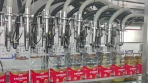
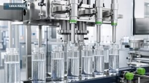
- Diving or bottom-up nozzle: can reduce the free-fall distance for products that foam, splash, or require the nozzle to follow the rising product level.
- Positive shut-off or anti-drip nozzle: helps control products that continue to flow after the metering stroke.
- Suck-back: can help pull a stringy product away from the nozzle tip at the end of a fill. Its effect must be checked with the real product and settings.
- Large-bore passage: may be required for high viscosity or particles, but the full route through the hopper outlet, valves, hoses, and nozzle must be checked together.
Verify every wetted component
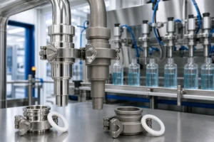
Do not approve the machine based only on a statement such as “stainless steel construction.” Ask for a wetted-parts list covering the hopper, product pipes, pump or piston components, valves, nozzle, hoses, seals, gaskets, and any recirculation path. Depending on the product, the review may include SS316L, PTFE, compatible elastomers, PP, PVDF, or another tested material. The final choice must be based on product compatibility, cleaning chemicals, temperature, and the applicable production standard.
General filling-machine selection matrix
Use this matrix to compare the questions developed in the following sections. It does not select a final configuration without a real-product trial.
On a small screen, swipe horizontally to compare every selection factor.
| Product characteristic | Candidate dosing arrangement | Nozzle requirement | Contact material | Bottle consideration | Cleaning requirement | Automation recommendation | Important validation test |
|---|---|---|---|---|---|---|---|
| Free-flowing, non-foaming liquid | Gravity-fed timed filling where reservoir head and timed-dose repeatability are validated; pressure-assisted timed flow with a stable supply; a suitable pump or flow-meter system may also fit | Clean shut-off; splash control where needed | Confirm formula and cleaning compatibility | Check neck opening, bottle stability, and fill level | Drainability and routine rinse or wash procedure | Inline automatic filling when the container supply and downstream process are stable | Repeatability from start-up to normal operating temperature |
| Foaming detergent or shampoo | Metering principle selected by viscosity and formula | Diving or bottom-up fill with controlled flow profile | Verify chemical and seal compatibility | Allow headspace and check narrow-neck behavior | Confirm foam residue removal and rinse procedure | Automatic filling after foam-control settings are proven | Fill at production temperature and observe foam collapse time |
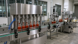
| Smooth, high-viscosity sauce, cream, or paste | Piston or suitable positive-displacement pump | Positive shut-off, anti-drip, or suck-back as required | Food- or product-compatible wetted path | Confirm opening size and container support | Quick access to product path; validate changeover procedure | Multi-head inline system when feeding can support parallel filling | Real-product speed, cut-off cleanliness, and weight or volume sample test |
| Viscous product with particles | Piston or another validated positive-displacement arrangement | Large product passage with controlled shut-off | Confirm abrasion, food-contact, and cleaning requirements | Wide opening preferred; verify soft-container handling | Open and inspect valves, passages, and dead spaces | Automatic multi-head filling only after feed rate and particle passage are proven | Use the largest normal particle concentration and the least favorable realistic temperature |
| Corrosive or solvent-containing liquid | Compatible gravity-fed timed, pump, flow-meter, or weight-based system | Controlled shut-off and fume or splash management as required | Compatibility-tested plastics, metals, hoses, and seals | Check container material and grounding or safety requirements | Define safe flush, drainage, ventilation, and operator protection | Automation level based on hazard review and local rules | Material compatibility and safety review with the actual formula |
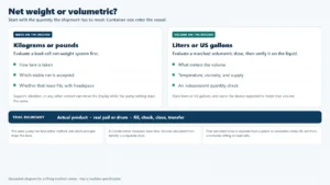
| Product sold or controlled by net mass | Net-weight filling or volumetric filling with a validated weighing control plan | Fast and fine cut-off suited to the product | Confirm product and cleaning compatibility | Rigid, repeatable support on the weighing station | Protect the load-cell area while maintaining access | Automatic system after vibration and settling time are validated | Scale resolution, tare variation, legal requirements, and filled-sample study |
4. Match the Machine with the Bottle and Container
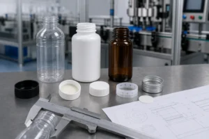
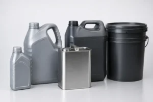
The container affects nozzle spacing, bottle control, filling speed, and clean cut-off. Send both empty and filled samples when possible. A soft PET bottle may deform under guide pressure. A narrow opening may limit nozzle diameter or make stringing more visible. A wide jar may accept a larger nozzle but still need accurate centering.
- Material and rigidity: PET, HDPE, glass, metal, and flexible containers require different handling pressure and support.
- Opening: record the inner diameter, neck height, and any foil or liner that changes the downstream process.
- Shape and center of gravity: tall, flat, oval, and irregular containers may need guides, spacing screws, neck locators, or dedicated fixtures.
- Fill range: confirm whether one machine must cover several container sizes and how often the format changes.
- Cleanliness at the rim: define the acceptable residue before sealing or capping.
Container capacity is not the fill quantity. A jar rated in mL does not establish how many grams of a product it holds. Confirm the target mass or volume separately, allowing for product density at filling temperature and the required headspace.
Review the bottle, cap, label, and coding position together. Check that the filler's discharge height, conveyor level, bottle pitch, and control signals match the next process.
5. Choose Machine Format and Automation Level
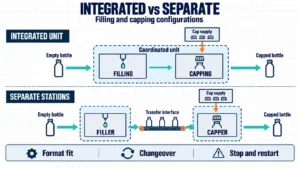
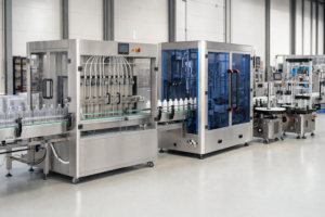
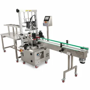
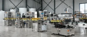
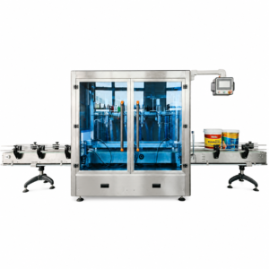
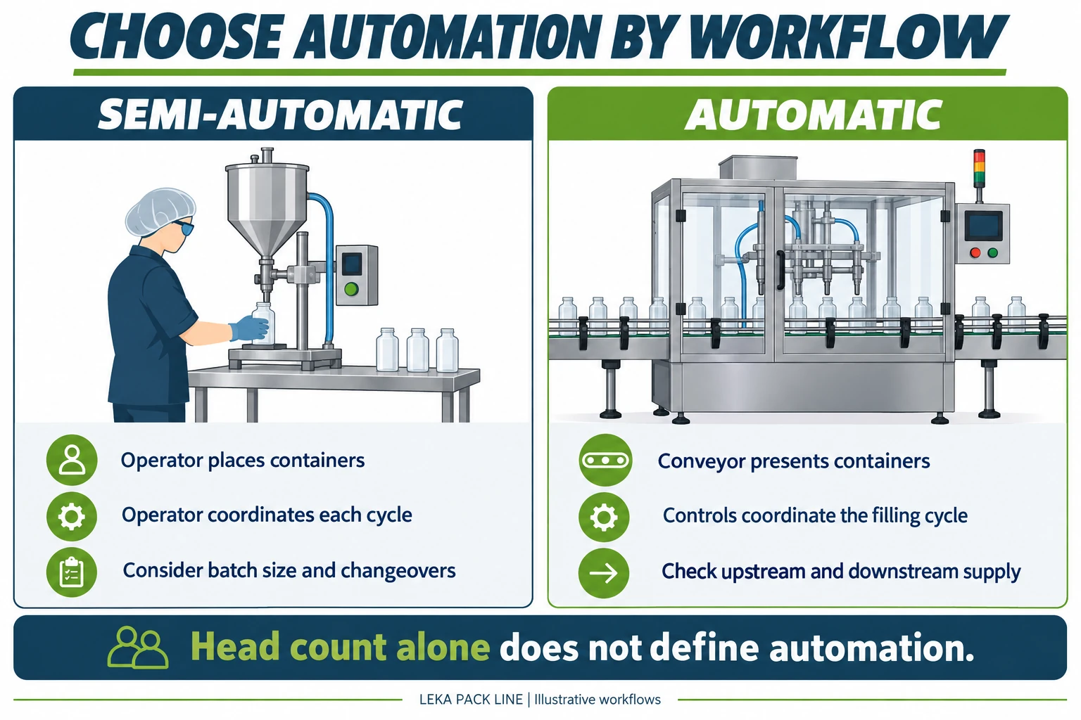
Machine format describes how containers move and how the filling stations are arranged. A bench or semi-automatic machine can suit product development, frequent changes, or low-volume batches. An inline automatic filler suits stable container feeding and continuous production. A rotary system may be considered for high-volume applications where the product, container, and line balance justify it.
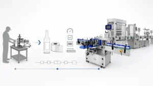
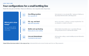
Choose automation by the complete operating plan, not by the word “automatic.” Confirm how bottles arrive, how caps and labels are supplied, how operators replenish materials, how rejects are handled, and where quality checks occur. If the project is ready for continuous automatic production, review the existing automatic bottle filling machine range. For smaller batches or staged investment, compare the semi-automatic filling machine options.
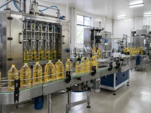
For a broader equipment comparison, review the filling machines range. If your project involves edible or industrial oil, check the automatic oil filling machine options against your product and container requirements.
6. Calculate Filling Heads and Validate Real Output
Filling-head count alone does not determine stable output. For an indexing filler that completes one full dose per bottle in each cycle, estimate its theoretical output using:
Theoretical bottles per hour = 3,600 × completed bottles per cycle ÷ cycle time in seconds. Use the number of containers actually filled in the cycle, not simply the number of installed nozzles.
Measure the complete cycle, including indexing, nozzle movement, dosing, cut-off, and settling; do not double-count operations that overlap. This estimate assumes repeated cycles without additional stops and is not a universal formula for rotary or multi-stage filling systems.
Measured accepted output = accepted filled bottles ÷ elapsed trial hours. Record the start and end times, included stops, and rejects. Report a short stable-running measurement separately from an average that includes adjustment, replenishment, or downtime. Product supply and downstream capping or labeling can limit the achievable line rate.
Ask the supplier to state the test product, fill volume, container, trial duration, included stops, and measurement method behind every output figure. For a lower-head-count reference, see the LEKA-FLSF-04-A 4-head servo liquid filling machine. For planning calculations, use the bottle filling machine output guide. These pages support equipment comparison; the final head count still requires a project-specific trial.
When comparing a larger configuration, review the multi-head servo filling machine and ask how its feeding capacity and complete cycle support your required output.
Verify fill tolerance separately from speed
For a fill specified by mass, record each empty container's tare and the corresponding filled gross weight under a consistent weighing procedure. Net product mass = gross weight − tare weight. Calculate each sample's signed deviation as (net mass − target mass) ÷ target mass × 100%. Check both underfill and overfill against the agreed limits; gross weights or an average alone do not demonstrate that every net fill meets tolerance.
7. Plan Cleaning, Changeover and Line Integration
Cleaning requirements should be defined before the product path is finalized. State whether the machine will run one product, several compatible products, or formulas that require controlled allergen or chemical changeover. Ask which parts are removed, which paths can be circulated, where the system drains, how seals and valves are inspected, and how the operator confirms that cleaning is complete.
Do not use “CIP” as a general label. A true clean-in-place process, a circulation-assisted wash, and quick-release manual disassembly are different arrangements. The quotation and acceptance plan should identify the actual procedure, utilities, cleaning chemicals, time, temperature, and components covered.
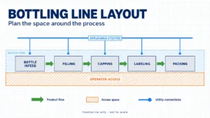
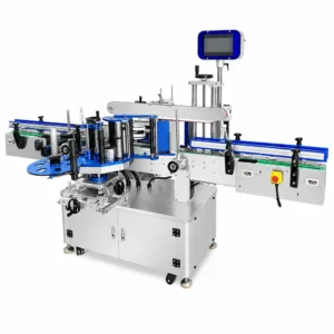
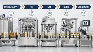
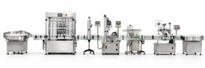
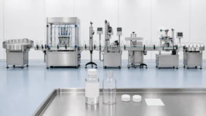
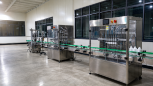
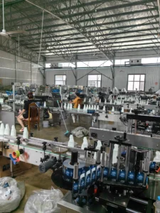
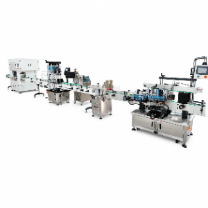
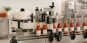
For line integration, confirm the real sequence and the control interface for bottle feeding, filling, sealing, cap sorting and placing, capping, coding, labeling, inspection, and discharge. The slowest stable process sets the line output. If the project needs these operations as one coordinated system, continue to the complete liquid filling line solutions page after the metering principle, container requirements, and trial conditions are defined.
8. Factory Trial: 340 g Peanut Butter in 400 mL Glass Jars
Case source: the following account was provided by LEKA for a factory trial on August 25, 2025, for a peanut butter producer in Spain. The customer remains anonymous. These are reported project observations, not an independently certified performance specification; the original count and weighing records are not reproduced here.
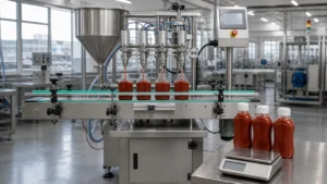
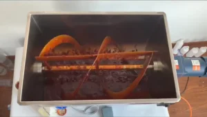
The product was a low-flow paste containing 3–5 mm peanut pieces, tested at a filling temperature of 45°C. LEKA reported no foaming or stringing under those conditions. The target fill was 340 g in a 400 mL glass jar, with an 80 mm jar diameter and an 80 mm round plastic cap. The jar capacity and target fill mass describe different requirements.
Configuration and test sequence
LEKA describes the tested configuration as a four-head servo-driven pump filler with wide-mouth anti-drip nozzles. The supplied account identifies quantity calculation from pump speed and rotations, rather than an independent flow-meter reading. Confirm the pump specification and dosing controls when comparing this configuration with a new project; the account does not establish independent servo control of every head.
LEKA reports a 24-hour no-product running check without collisions or stops, followed by a two-hour peanut butter trial without stoppage, fault, or repair. The reported output was measured during stable running after adjustment. Its exact measurement window was not supplied, so it should not be treated as a verified average across the full two-hour product trial.
Customer target and reported trial observations
| Trial item | Customer requirement | Reported observation | How to interpret it |
|---|---|---|---|
| Output | 500 bottles per hour at a 340 g fill. | LEKA reports an average stable rate of 1,200 bottles per hour after adjustment, for the tested peanut butter and 340 g target fill. | The count and timing record is not provided. Do not treat this reported stable rate as a verified full-run average or a general machine rating. |
| Fill tolerance | A fill error no greater than 1%. | Twenty filled jars were weighed with their glass containers included. No overweight jar was reported. | This gross-weight check does not establish net-fill accuracy or rule out underweight jars. It does not confirm that the 1% net-fill tolerance was achieved. |
| Running check | Stable operation with the actual product. | A 24-hour no-product run preceded a two-hour peanut butter trial. No stops, faults, or repairs were reported during the product run. | The no-product and product tests answer different questions; neither should be substituted for the other. |
| Cleaning | Clean the product path after the peanut butter trial. | LEKA reports running the machine with water containing cleaning agent at 60°C and a visibly clean result after about one hour. | This is a reported wash procedure, not evidence of complete automatic CIP or validated allergen or microbiological removal. |
LEKA reports that the trial passed the factory's acceptance requirements. That reported acceptance does not establish a verified net-fill accuracy result. For a similar product, agree on the jar, filling temperature, output measurement window, individual tare-and-net sample records, and cleaning acceptance method before approving the final configuration.
How trial evidence should change the buying decision
- Use real product rather than water when viscosity, particles, stringing, or separation affect the cycle.
- Keep the customer target, the machine's theoretical rating, and the measured trial result in separate rows.
- Validate stable output with the full product path and downstream equipment, not only the number of filling heads.
- Accept that speed, accuracy, particle passage, and clean cut-off may require a controlled compromise.
- Document unresolved alarms and target gaps before final machine approval.
9. Prepare Your Project Data Before Requesting a Machine
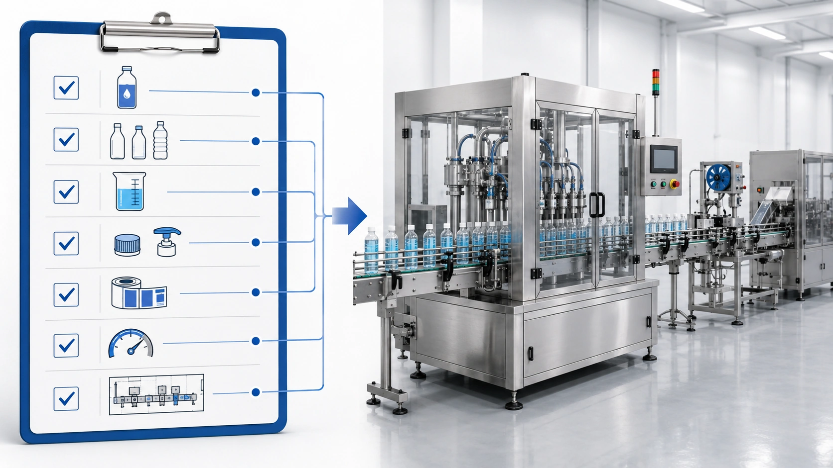
A useful quotation should be based on a defined product, container, operating target, and acceptance method. Send the following information before the machine configuration is finalized.
| Project information | What to provide | Why it changes the machine |
|---|---|---|
| Product | Name, formula or safety data where applicable, viscosity at filling temperature, density, foam, stringing, particles, corrosion, separation, and temperature range | Defines the metering principle, feeding method, nozzle function, wetted materials, and trial plan |
| Container | Photos, drawings, samples, material, dimensions, opening, rigidity, and all required fill sizes | Defines nozzle size and spacing, guides, centering, fill height, and change parts |
| Production target | Required bottles per hour, fill volume, shifts, expected efficiency basis, and future capacity | Defines head count, cycle target, feeding capacity, and automation level |
| Quality requirement | Permitted fill tolerance, sample method, tare control, inspection frequency, and applicable rules | Defines the metering and verification plan |
| Cleaning and changeover | Products per shift, allergen or contamination controls, cleaning chemicals, utilities, and available cleaning time | Defines product-path access, drainability, disassembly, and wash arrangement |
| Line integration | Cap, seal, label, code, inspection, conveyors, line direction, workshop drawing, voltage, air, and other utilities | Defines interfaces, line balance, layout, and control signals |
| Factory acceptance test | Test product, container quantity, duration, sampling plan, pass/fail criteria, and treatment of stops | Creates one measurable basis for final approval |
Additional planning guides
- Map the full bottle process with the bottling machine selection guide.
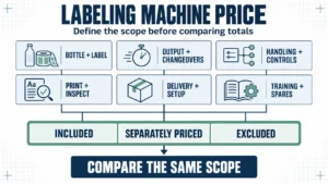
- Review quotation variables in the bottle filling machine price guide. For a detergent project, also consult the detergent filling machine price guide.
- Compare staged investment with the filling machine guide for small and medium factories.
- Prepare a supplier review with the liquid bottle filling machine manufacturer comparison.
10. Frequently Asked Questions About Automatic Liquid Filling Machines
Which information should I provide first?
Start with the product, its behavior at filling temperature, the container and opening, the fill range, target output, required tolerance, cleaning method, and the downstream packaging steps. Photos and drawings help, but representative samples are more useful for the final trial.
Which metering principle is best for a thick liquid?
Piston and suitable positive-displacement pump systems are common candidates, but viscosity alone is not enough to decide. Particle size, shear sensitivity, stringing, feeding conditions, temperature, fill range, and cleaning requirements must also be checked.
Does a servo system guarantee better filling accuracy?
No. A servo can improve control of motion, stroke, and speed profiles, but metering design, product supply, valve and nozzle performance, container handling, calibration, and test conditions still determine the result.
Is a servo-pump filler the same as a flow-meter filler?
No. A servo-pump filler can calculate a dose from calibrated pump rotations. A flow-meter filler uses the selected meter's measurement to determine the delivered quantity. A system may combine these components, so ask which signal actually controls the dose instead of judging by the word “servo.”
Can a diving nozzle stop all foam or dripping?
No. A diving motion can reduce free-fall distance, and shut-off or suck-back functions can improve cut-off for selected products. The result depends on the product, nozzle design, speed profile, temperature, and container, so it must be tested.
How do I choose the number of filling heads?
Calculate the required cycle from the fill volume and product discharge rate, then include indexing, nozzle movement, cut-off, and downstream line balance. Confirm the result with the actual product rather than multiplying a water-test speed by the number of heads.
Can one machine run several products and bottle sizes?
Often it can, but the usable range depends on the metering unit, product compatibility, cleaning risk, nozzle spacing, guides, container opening, and change parts. Group the products by flow behavior and cleaning requirement before approving one shared configuration.
What should a factory trial record?
Record the product and temperature, fill size, container, trial duration, included stops, stable output, sample plan, scale resolution, deviations, alarms, residue at the bottle rim, cleaning observations, and the exact configuration used.
Does weighing filled jars prove net-fill accuracy?
Not by itself. A filled jar's gross weight includes the container. To verify a target stated in grams, subtract the corresponding tare weight and check each net result against both lower and upper acceptance limits. “No overweight jars” does not establish that none were underfilled.
When should I plan the complete filling line?
Plan the interfaces early whenever sealing, cap handling, capping, coding, labeling, inspection, or discharge can limit output or change container control. Confirm the metering principle and container requirements, then balance the connected equipment around a stable rate verified with the real product.
Ready to Send Your Complete Filling Project Details?
Send your product details, bottle photo or sample, fill range, cap and label information, target output, cleaning needs, and factory layout. LEKA Pack Line can review the filling principle, machine format, nozzle configuration, and line connection required for your project.